


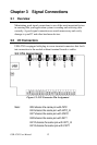
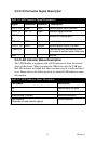

3.2.2 I/O Connector Signal Description
Table 3.1: I/O Connector Signal Descriptions
Signal Reference Direction Description
IDI<0~15> GND Input Isolated digital input channels
INT<0,1> INT_G Input Interrupt trigger sources.
INT<0,1>_
G
- - Ground for interrupt pins.
CNT<0,1> GND Input Isolated input counters
IDO<0~15> GND Output Isolated digital output channels
COM<0,1> - - Common pins for connecting induc-
tive loads of isolated output channels
GND - - Ground
3.2.3 LED Indicator Status Description
The USB Module is
equipped with a
LED indicator to show the
current
status
of
the device. When
you plug
the USB
device into the USB
port,
the LED
indicator will blink
five times
and then
stay lit
to indicate that it
is on.
Please refer to
the
following table for detailed LED
indicator
status
information.
Table 3.2: LED Indicator Status Description
LED Status Description
On Device ready for work
Off Device not ready to work
Slow Blinking (5 times) Device initialization
Fast Blinking
(Depends on data transfer speed).
Device working
13 Chapter 3