


INSTALLATION
6
For Ultrasonic Point Level Switches LVUN-600 Series
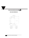
CONTROL UNIT
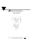
Refer to the typical installation diagram and control unit dimensions when
installing the control unit.
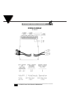
CALIBRATION PROCEDURE
After the installation is complete, the system must be calibrated for proper opera-
tion.
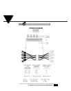
1. Connect the sensor cable to electronics as shown in wiring diagram.
2. Connect power as per wiring diagram.
3. Turn the power on.
4. Allow the liquid to rise above the sensing point until the relay is energized.
5. Allow the liquid to fall below the sensing point, relay should de-energized.
6. Repeat steps 4 and 5.
7. Unit is now calibrated. When the liquid level is above the sensing point, the
relay will be energized. When the liquid level is below the sensing point,
the relay will be de-energized.
MAINTENANCE
PREVENTIVE MAINTENANCE
Electronics are constructed with solid state components.
Periodically, check and clean the sensor(s) when used with
liquids which cause a coating to build up on the sensor. No
other maintenance is required.
CLEANING
If the pipe or vessel to which the sensor is mounted is to be steam cleaned or
cleaned with abrasive detergents, remove the entire unit before cleaning by:
1. Disconnecting the power at source.
2. Opening the housing cover.
3