


INSTALLATION OF PSW-141 PRESSURE
SWITCH
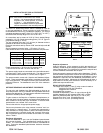
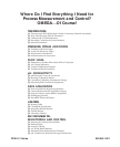
Each switch is calibrated in the vertical
position. It is recommended the switch be
mounted in the vertical position, as viewed
in Figure 1. Any adjustments to the
setpoint or deadband should be performed
with the instrument in the mounted position.
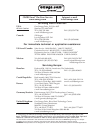
The PSW-141 differential pressure switch is suitable for clean air
or inert gas applications. If dust is present, a small in-line filter is
recommended to insure long, trouble-free operation. The normal
operating temperature range is from 0°C to 45°C (32°F to 115°F),
and the normal humidity range from 10% to 90% R.H.
Air connections are by means of 3/16 (4.75mm) barbed fittings
suitable for 1/4 O.D. polyethylene tubing (6mm), 1/8 I.D. Tygon or
polyurethane tubing (3 - 4mm).
The two mounting holes are 0.19 (4.8mm) in diameter and are
suitable for #8 or #10 mounting screws.
Electrical connections are by means of 3/8 terminal strips with #6
screws.
Spacing between mounting holes: 4.75 inches (121 mm).
Care should be taken not to exceed the maximum overpressure.
NOTE:
Figure 1
Power consumption is .35 W for the DC powered units,
1.70 W for the 24 Vac and 1.90 W for the 120 Vac.
The power supply leads are connected to the two leftmost termi-
nals (terminals 1 and 2) on the terminal strip. The relay terminals
are accessed across terminals 3, 4, and 5, refer to Figure 1.
The pressure switch comes with Setpoint and Deadband Adjust-
ments. These are adjusted at the factory to activate on either fall-
ing or rising pressure. The setpoint is factory set to activate at the
maximum pressure. The deadband is set to 5% of the maximum
pressure.
SETPOINT/DEADBAND ADJUSTMENT PROCEDURE
The set point and deadband are field adjustable so long as an
accurate pressure source is available and a qualified technician
performs the adjustments. The low pressure switches are extremely
sensitive to sudden pressure changes.
To gain access to the Setpoint or Deadband potentiometers re-
move the black hole plugs above the Setpoint and Deadband la-
bels, located on the top left of the instrument. To access either
potentiometer use a slotted 3/32 screw driver.
Connect the switch to its appropriate power supply.
Connect an ohmmeter to the relay contacts common and nor-
mally closed or normally open. If a switch was ordered with a
relay activated on Rising Pressure and the ohmmeter terminals
are connected to the normally closed and common of the relay,
with no pressure applied, the ohmmeter should read 0 or closed,
refer to Table 2.
Deadband Adjustment
To set the deadband to zero, turn the Deadband potentiometer
fully counter-clockwise . Zero deadband will cause the relay to
chatter. It is recommended that some amount of deadband be
used. Turning the deadband potentiometer clockwise increases
the deadband.
Setpoint Adjustment
Apply full pressure, (or the pressure at which the setpoint is to
activate). Rotate the 20 turn Setpoint potentiometer, until the ohm-
meter changes state. Turn clockwise to increase the set point and
counter-clockwise to decrease the set point
Slowly decrease the pressure until the relay deactivates. The dif-
ference between the pressure at which the relay deactivates and
the pressure at which the relay activates is the deadband. If more
deadband is required, turn the deadband potentiometer and re-
peat the previous steps. Adjustment of the deadband will have a
slight effect on the set point, therefore it will be necessary to re-
peat these steps several times.
RELAY SPECIFICATIONS
The output of the SPDT (1 Form C) relay contact is rated at:
5A @ 30 VDC/120 VAC Resisitive
4A @ 240 VAC Resistive
Gold-plated relay contacts.
Electrical life expectancy: 100 x 10
3
ops. minimum @ 5A
Isolation between coil and contacts: 2000 VAC 1 minute
Maximum switched power: 600 VA (AC) or 120 W (DC)
Operate Time: 8 ms, max (Excluding Bounce)
Release Time: 4 ms, max (Excluding Bounce)
Table 2
yaleR:tuptuOretemmhO
yllamroNdnanommoC
desolC
erusserP
gnisiR
erusserP
gnillaF
erusserP
deilppAoN
erusserP
)0(desolC)LO(nepO
erusserPlluF)LO(nepO)0(desolC
elbaTerusserprevOyratnemoMefaSmumixaM
egnaR erusserprevO
hsilgnE cirteM hsilgnE cirteM
H"0.1ot"1.0
2
O
H"0.01ot"0.2
2
O
H"11
2
DISP5otO
DISP51otDISP6
DISP03otDISP61
aP052ot52
aPk5.2ot5.0
aPk53ot7.2
aPk001ot04
aPk002ot011
H"8
2
O
DISP5
DISP02
DISP03
DISP06
aPk2
aPk53
aPk041
aPk002
aPk024
PSW-141 Series M-3488 / 0011