


INTRODUCTION
The OMEGA differential pressure switch is a
precision built U.L. approved control device
which features a mechanical snap action switch.
Controllers are available for operation on vari-
ous pressure differentials with fixed or variable
switching differentials. The standard electrical
switch is SPDT and is available with various
electrical characteristics.
Two SPDT switch elements mounted together
are available. Various wetted material construc-
tions for compatibility with a wide range of
pressure media may be obtained.
The snap action differential pressure switch is
furnished in the standard NEMA 4/4X and explo-
sion proof NEMA 7 and 9 enclosure styles. Both
enclosures are epoxy coated aluminum castings.
INSTALLATION
These controls are precision instruments and
should never be left with internal components
exposed. During installation insure that covers
are in place and conduit openings are closed
except when actually working on the control.
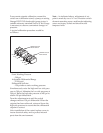
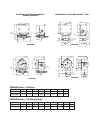
MOUNTING DSW490 AND DSW790 SERIES
There are three holes external to the enclosure
for surface mounting. Location of these holes is
shown on the general dimension drawing. They
may also be mounted directly on pressure line
using the pressure connections.
ELECTRICAL CONNECTIONS
Remove cover
DSW490 Series – two screws hold cover to
enclosure
DSW790 Series – cover unscrews
CONDUIT CONNECTIONS
Note – It is recommended that Teflon
®
tape or
other sealant be used on conduit, bushing or
plug threads to ensure integrity of the enclosure.
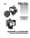
INSTALLATION AND MAINTENANCE OF THE
DSW490B AND DSW490B SERIES
OMEGA
®
SNAP ACTION SWITCHES
FOR DIFFERENTIAL PRESSURE CONTROL
DSW490 series standard – one
3
⁄
4 NPT conduit
hole right side.
DSW790 series standard – two
3
⁄
4 NPT conduit
holes with one permanent plug. NEMA 7 & 9
enclosures require proper conduit seals and
breathers as per the National Electrical Code.
DSW490 SERIES
SPDT
– Wire directly to the switch according to
circuit requirements.
2-SPDT – Dual switching elements consist of
two SPDT switches mounted together in a
bracket. Switches are calibrated to have simul-
taneous operation within 1% of range either on
increasing or decreasing pressure but not in
both directions. Wire directly to the front and
rear switch according to circuit requirements.
Leads are provided on rear switch color coded
as follows:
Common – White
Normally Closed – Red
Normally Open – Blue
When hermetically sealed switch element(s) are
supplied, the lead color coding is as follows:
Common – White
Normally Closed – Red
Normally Open – Blue
DSW790 SERIES
SPDT
– Wire directly to the switch according to
circuit requirements.
2-SPDT – Wire to front switch terminal block
(left) and rear switch terminal block (right) as
marked. Strip insulation
5
⁄
16,˝ insert in proper
terminal connector and tighten clamping screw
to secure.
ADJUSTMENT OF SETPOINT
DSW490 & DSW790 Series – A single setpoint
adjustment nut (
7
⁄
8˝) is located centrally at the
bottom on the inside of the enclosure.