


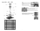

4
Flush Ceiling Mount
For installations with low ceilings, the flush ceiling mount
should be used. Note: cable management is not available
with the flush mount. Proceed to step 3.
Wall Mount
With the addition of the OmniMount PMD-WM wall mount
(sold separately); the PMD can be mounted to a wall instead
of the ceiling. This is particularly useful for small confer-
ence/classrooms where a ceiling mount is impractical. Refer
to the PMD-WM installation instructions.
Extended Ceiling Mount
For installations that require a ceiling drop in
excess of 18”, standard 1 ½” pipe may be used
to extend the standard pipe drop assembly.
Pipe extension should be cut to the required
additional length, threaded on both ends, and
then attached to the standard pipe drop as-
sembly with a pipe coupler (not supplied).
Note: Orient the cable management port on
the pipe drop assembly so that it faces the
projector cable drop.
Standard Ceiling Mount
Press plastic cover (D) into place over ceiling plate.
Attach pipe drop assembly (C) to ceiling plate with three 5/8” hex
screws (H).
Note: Orient the cable management port on the pipe drop assem-
bly so that it faces the projector cable drop.
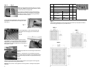
Step 3
Determine type of installation:
• Standard Ceiling Mount
• Extended Ceiling Mount
• Flush Mount
• Wall Mount
Step 2
With an electronic stud finder, locate center of ceiling stud in desired mounting loca-
tion. Unscrew ceiling plate (E) from Projector Mounting top plate (A). Use ceiling plate
as a template, and mark mounting hole locations. Drill mounting holes to a depth of 3”
using a 3/16” drill bit. Mount ceiling plate to stud with 5/16” lag bolts (J).
5
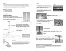
Step 4
Gently pull the extension tube of the pipe drop as-
sembly down to the required projector height. Rotate
extension tube so that adjustment screw holes are
visible through the support tube. (Fig. 1)
Secure the pipe position by installing ½” long hex
screws (I) into adjustment screw holes. For a cleaner
appearance, insert plastic plugs (K) into unused
holes on extension tube.
Fig. 1
Thread ¼” hex head set screw (F) into side of pipe collar,
on top projector mounting plate (A). (Fig. 3)
Note: If necessary, screw in tilt knob to gain access to the
set screw hole.
Fig. 3
Loosely thread top projector mounting plate (A) onto threaded
portion of pipe drop.
Position top projector mounting plate into desired orientation
(horizontal or vertical), and then tighten set screw (F). (Fig. 4)
Separate top and bottom projector mounting plates
(A&B), by sliding them apart. (Fig. 2)
Fig. 2
Thread cable bundle through cable management port at top of
pipe assembly, down through the pipe assembly, and then out
through the cable management port on the rear of the projector
mounting plate. (Fig. 5) (Standard ceiling mount only) Be sure
to leave enough cable to reach the mounted projector.
Fig. 4
Fig. 5
Flush Ceiling Mount
For flush ceiling mount, loosely thread top projector
mounting plate directly onto threaded portion of ceiling
plate. Note: Plastic cover is not used for flush mount.