


the transmit wavelength of the Channel Port. Typically, the receiver of a dual ber
transceiver has an operating center wavelength of 1260nm to 1610nm. Verify the
external transceiver’s optical parameters before using.
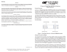
Figure 2: 1-Channel Add/Drop MUX/DEMUX
Common Port (Left and Right)
The aggregated wavelengths from the Channel Ports are transmitted and received
over the single-ber Common Port. As shown in Figure 2, there are Left and Right
Common Ports on the CWDM/AD module. Common Port Left (COM-L) and Common
Port Right (COM-R) are internally connected to pass through all wavelengths not
dropped or added by the specic CWDM/AD model Only the specic wavelengths
of the model selected will be dropped to the appropriate Channel Port. Common
Port Left drops and adds wavelength trafc from Channel Port Left and Common
Port Right drops and adds wavelength trafc from Channel Port Right.
Installation
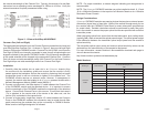
1. Carefully slide the module into an open slot in an iConverter chassis. Align
the module with the installation guides and ensure that the module is rmly
seated against the backplane. Secure the module by fastening the front panel
thumbscrew (push in and turn clockwise to tighten) to the chassis front. The
CWDM/AD module requires no external power, however, if management is
required, the module must be installed in an iConverter powered chassis with a
Network Management Module (NMM2 model 8000N-1).
2. Connect a single-mode, dual ber duplex LC cable between the Channel Port
of the CWDM/AD module and the attached device. It is important to ensure
that the wavelength of the CWDM/AD matches the wavelength of the attached
device. Connect both Channel Ports in this manner. Ensure that the transmit
(Tx) is attached to the receive side of the device at the other end, and the
receive (Rx) is attached to the transmit side.
3. Connect a single-mode, single-ber simplex LC cable between the Common
Ports on the CWDM/AD modules (this connection may be made through ber
patch panels since the modules may not be co-located) or CWDM/X module.
Make sure the Left/Right designation is followed.
Page 2
NOTE: For proper installation, a network diagram indicating port designations is
recommended.
NOTE: The
iConverter CWDM/AD modules can not be installed in slots 4, 8, 12 and
16 of a 19-Module Chassis or in the top slot of a 2-Module Chassis or in a 1-Module
Redundant Power Chassis.
Design Considerations
iConverter CWDM/AD modules are passive devices that require no external power.
Attenuation (signal loss) of less than 1.9dB will be realized through each port on
the module (see the CWDM/AD Data Sheet for exact attenuation specications
for model used). Detailed calculations should be performed for each ber optic
link in the network to ensure the proper optical devices are specied with sufcient
transmitter power.
When calculating optical loss, ensure that the total attenuation, plus a safety factor
(typically 3dB), does not exceed the optical power budget. The optical power budget
is the difference between the transmitter optical output power and the receiver’s
optical sensitivity.
The transmitter optical output power and receiver optical sensitivity values can be
obtained from the manufacturers of the respective equipment.
For more information, access Omnitron’s documentation download web page to
view all relevant documents:
http://www.omnitron-systems.com/downloads.php
Model Numbers
Page 3
Model Type Model Number
Channel Port
ITU Center Wavelength (nm)
Tx/Rx
Left Channel Right Channel
1-Channel
OADM
8878-27 1271/1291 1291/1271
8878-31 1311/1331 1331/1311
8878-35 1351/1371 1371/1351
8878-39 1391/1411 1411/1391
8878-43 1431/1451 1451/1431
8878-47 1471/1491 1491/1471
8878-51 1511/1531 1531/1511
8878-55 1551/1571 1571/1551
8878-59 1591/1611 1611/1591