


Channel Port
The Channel Ports transmit and receive signals on specic CWDM wavelengths. Each
Channel Port supports a different transmit and receive wavelength based on the CWDM/X
model. The Channel Ports are multiplexed onto and demultiplexed from the Common
Port.
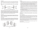
Figure 3 shows a pair of 2-Channel CWDM/X modules connected via a single-mode,
single-ber cable. A total of four wavelengths are supported on each 2-Channel CWDM/X
module.
Figure 3: A Pair of 2-Channel MUX/DEMUX Modules
When connecting external dual ber transceivers to the Channel Port, select an optical
transceiver that matches the receive wavelength of the specic Channel Port. Since the
Channel Port uses two different wavelengths over dual ber, one wavelength for transmit (Tx)
and a different wavelength for receive (Rx), the receiver of the external dual ber transceiver
must have the capability to detect the transmit wavelength of the Channel Port. Typically,
the receiver of a dual ber transceiver has an operating center wavelength of 1260nm to
1610nm. Verify the external transceiver’s optical parameters before using.
Common Port
The Common Port transmits and receives the aggregated wavelengths connected to the
Channel and Expansion Ports over a single-ber common link. CWDM/X modules are always
used in pairs. When connecting two CWDM/X modules, the COM-L port is connected to the
COM-R port on the matching pair.
Expansion Port
The optional Expansion Port (EXP) enables the cascading of two CWDM/X modules as
shown in Figure 4. The Expansion Port supports the cascading of two 4-Channel modules
or the cascading of a 4-Channel module with a 2-Channel module by connecting to the
Common Port of another CWDM/X module. When cascading, make sure the wavelengths
of the Channel Ports on each module are unique and not duplicated.
Figure 4: Two Cascaded 4-Channel MUX/DEMUX Modules
Page 2
Installation
1. Carefully slide the module into an open slot in an
iConverter chassis. Align the module
with the installation guides and ensure that the module is rmly seated against the
backplane. Secure the module by fastening the front panel thumbscrew (push in and
turn clockwise to tighten) to the chassis front. The CWDM/X module requires no external
power, however, if management is required, the module must be installed in an
iConverter
powered chassis with a Network Management Module (NMM2 model 8000N-1).
2. Connect a single-mode, dual ber duplex LC cable between the Channel Port of the
CWDM/X module and the attached device. It is important to ensure that the wavelength
on each ber strand of the CWDM/X matches the wavelengths of the attached device.
Connect all Channel Ports in this manner. Ensure that the transmit (Tx) is attached to
the receive side of the device at the other end, and the receive (Rx) is attached to the
transmit side.
3. Connect a single-mode, single-ber simplex LC cable between the Common Ports on
the CWDM/X modules (this connection may be made through ber patch panels since
the modules may not be co-located). Ensure that the COM-L port at one end connects
to the COM-R port at the other end.
4. When cascading two 4-Channel CWDM/X modules or a 4-Channel and a 2-Channel,
connect a single-mode single-ber simplex LC cable between the Common Port on
one CWDM/X module and the Expansion Port on the other CWDM/X module (see
Figure 4). Ensure that the wavelengths of the Channel Ports on the CWDM/X modules
are unique.
NOTE: The iConverter CWDM/X modules can not be installed in slots 4, 8, 12 and 16 of
a 19-Module Chassis or in the top slot of a 2-Module Chassis or in a 1-Module Redundant
Power Chassis.
Design Considerations
iConverter CWDM/X modules are passive devices that require no external power. Attenuation
(signal loss) of less than 2.7dB will be realized through each port on the module (see
the CWDM/X Data Sheet for exact attenuation specications for each model). Detailed
calculations should be performed for each ber optic link in the network to ensure the proper
optical devices are specied with sufcient transmitter power.
When calculating optical loss, ensure that the total attenuation, plus a safety factor (typically
3dB), does not exceed the optical power budget. The optical power budget is the difference
between the transmitter optical output power and the receiver’s optical sensitivity. The
transmitter optical output power and receiver optical sensitivity values can be obtained from
the manufacturers of the respective equipment.
For more information, access Omnitron’s documentation download web page to view all
relevant documents:
http://www.omnitron-systems.com/downloads.php
Page 3