


Page 15
Page 10 Page 11
Page 12
Page 9
Page 14
Page 16
SPECIFICATIONS
Form: 040-12200-001A 9/08
Warning
The operating description in this Instruction Manual
is for use by qualified personnel only. To avoid
electrical shock, do not perform any servicing of
this unit other than that contained in the operating
instructions, unless you are qualified and certified
to do so by Omnitron Systems Technology, Inc.
Warranty
This product is warranted to the original purchaser
against defects in material and workmanship for a
period of TWO YEARS from the date of shipment.
A LIFETIME warranty may be obtained by the original
purchaser by REGISTERING this product with
Omnitron within 90 days from the date of shipment.
TO REGISTER, COMPLETE AND MAIL OR FAX
THE ENCLOSED REGISTRATION FORM TO THE
INDICATED ADDRESS. Or you may register your
product on the Internet at http://www.omnitron-
systems.com. During the warranty period, Omnitron
will, at its option, repair or replace a product which
is proven to be defective.
For warranty service, the product must be sent to
an Omnitron designated facility, at Buyer’s expense.
Omnitron will pay the shipping charge to return the
product to Buyer’s designated US address using
Omnitron’s standard shipping method.
Limitation of Warranty
The foregoing warranty shall not apply to defects
resulting from improper or inadequate use and/or
maintenance of the equipment by Buyer, Buyer-
supplied equipment, Buyer-supplied interfacing,
unauthorized modifications or tampering with
equipment (including removal of equipment cover
by personnel not specifically authorized and
certified by Omnitron), or misuse, or operating
outside the environmental specification of the
product (including but not limited to voltage, ambient
temperature, radiation, unusual dust, etc.), or
improper site preparation or maintenance.
No other warranty is expressed or implied. Omnitron
specifically disclaims the implied warranties of
merchantability and fitness for any particular
purpose.
Exclusive Remedies
The remedies provided herein are the Buyer’s sole
and exclusive remedies. Omnitron shall not be liable
for any direct, indirect, special, incidental, or
consequential damages, whether based on contract,
tort, or any legal theory.
TECHNICAL SUPPORT:
For help with this product, contact Omnitron’s Tech.
Support:
Phone: (949) 250-6510
Fax: (949) 250-6514
Address: Omnitron Systems Technology, Inc.
140 Technology #500
Irvine, CA 92618 USA
E-mail: support@omnitron-systems.com
URL: http://www.omnitron-systems.com
SPECIFICATIONS (CONT.)
TROUBLESHOOTING GUIDE
Problem:
The Power LED does not illuminate after installation is
complete.
Possible Causes:
A. Confirm that the power supply is connected.
B. Confirm that the correct power supply is being used.
Problem:
The Fiber Optic link LED does not illuminate after
installation is complete.
Possible Causes:
A. Confirm that the fiber optic cable is properly
connected to the
miConverter GX/T and the remote
fiber optic device.
B. Confirm that the fiber cable type matches the fiber
transceiver type (multimode, single-mode) on the
miConverter GX/T
C. If using a dual-fiber model, confirm that the
transmitter (Tx) is attached to the receiver side of its
link partner, and that the receiver (Rx) is attached to
the transmitter.
D. If using a single-fiber model, confirm that the Tx
wavelength on the
miConverter GX/T matches the Rx
of the connected fiber optic device.
Problem:
The UTP link LED does not illuminate after installation
is complete.
Possible Causes:
A. Confirm that the UTP cable is connected properly
to the
miConverter GX/T and the attached UTP device.
B. Confirm that the UTP cable pin-out is correct (EIA/
TIA-568-A).
C. Verify the
miConverter GX/T UTP port is configured
with the proper settings based on the attached device
(AN or MAN, 1000,100 or 10, HD or FD).
Note: If corrective actions do not resolve your
situation, please contact Omnitron Systems
Technical Support.
Page 13
Model miConverter GX/T
Description 10/100/1000BASE-T UTP to 1000BASE-X
Fiber Converter
Protocols
10BASE-T, 100BASE-TX, 1000BASE-T,
1000BASE-X
Frame Size
10,240 byte max frame size
Cable Types
UTP
EIA/TIA 568A/B, Category 5 and higher
Fiber
Multimode: 50/125, 62.5/125, 100/140 um,
Single-mode: 9/125 um
Connector Types
UTP
RJ45
Fiber
Dual Fiber
Single-Fiber
SFP
SC, ST
SC
LC
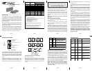
LED Display Pwr, AN, F/O Lk,
UTP-10, UTP-100, UTP-1000
Power Requirements
DC Power
(Typical)
5 to 12VDC
0.35A @ 5VDC
DC Power Connector 2.5mm DC Jack
or
2 Pin Terminal Connector
AC Power Adapter
[US]
100-120VAC/60Hz
0.02A @ 120VAC
AC Power Adapter
[Universal or
Country/Region Specific]
100-240VAC/50-60Hz
0.02A @ 120VAC
Dimension
W:1.71" x L:4.10" x H:0.84"
Weight
without power adapter
5 oz.
with USB power adapter
6 oz.
with AC power adapter
[US]
12 oz.
Compliance
Operational Temperature
Standard
0 to +50
o
C
Storage Temperature
-50 to +80
o
C
Humidity
(non-condensing)
5 to 95%
Altitude
-100m to 4000m
MTBF [hrs]
without power adapter
878,000
with
US or
Country/Region Specific
power adapter
250,000
with
Universal power adapter
100,000