


Any other DIP-Switch configuration will disable
Symmetrical Fault Detection mode.
NOTE: Converters in SFD mode must be deployed in pairs.
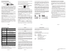
Board Mounted DIP-Switch Settings
BPAEN
BPBEN
MAN
MAN
=
=
=
=
Backplane “A” Enabled
Backplane “B” Enabled
P1 Manual
P2 Manual
AN
AN
=
=
Off
Off
P1 Auto Negotiate
P2 Auto Negotiate
ON
Fig. 4 Board Mounted DIP-Switches
Backplane A Enable “BPAEN” DIP-Switch
When the “BPAEN” DIP-Switch is in the right position,
the A 10/100 Ethernet backplane port is enabled. This
port allows connection to an adjacent module (in the
same chassis) via the backplane A link of the chassis.
When the “BPAEN” DIP-Switch is in the left “off”
position (factory setting), the A port is isolated from
the backplane.
Backplane B Enable “BPBEN” DIP-Switch
When the “BPBEN” DIP-Switch is in the right position,
the B 10/100 Ethernet backplane port is enabled. This
port allows connection to an adjacent module (in the
same chassis) via the chassis’ backplane B link. When
the “BPBEN” DIP-Switch is in the left “off” position
(factory setting), the B port is isolated from the
backplane.
Fiber Port 1 Auto/Manual “ P1 AN/MAN” DIP-Switch
When the P1 AN/MAN switch is in the “AN” (left) position
(factory setting) it enables Port 1 to determine duplex
mode automatically. If the device connected to Port 1
cannot provide the proper signal to indicate its own
mode of operation, then the DIP-Switch should be set
to the “MAN” (right) position, forcing Port 1 to
Full-Duplex mode.
Fiber Port 2 Auto/Manual DIP-Switch (P2 AN/MAN)
When the P2 AN/MAN switch is in the “AN” (left)
position (factory setting) it enables Port 2 to
determine duplex mode automatically. If the device
connected to Port 2 cannot provide the proper signal
to indicate its own mode of operation, then the
DIP-Switch should be set to the “MAN” (right) position,
forcing Port 2 to Full-Duplex mode.
NOTE: When a fiber port is in manual mode, sometimes
a link-up will not occur with other devices. Both devices
must be set to the same mode (either Manual or
Auto-Negotiate) for the link-up to occur.
LED INDICATORS
LED Color Description
Pwr: Yellow On--Power
F/O P1 FDX: Green On--Full-Duplex detected
F/O P1 Lk/Act: Green On--Link / Blink--activity
F/O P2 Lk/Act: Green On--Link / Blink--activity
F/O P2 FDX: Green On--Full-Duplex detected
Page 15
Page 10 Page 11
Page 12
Page 9
Page 14 Page 16
Page 13
Warning
The operating description in this Instruction Manual is for use by qualified
personnel only. To avoid electrical shock, do not perform any servicing of
this unit other than that contained in the operating instructions, unless you
are qualified and certified to do so by Omnitron Systems Technology, Inc.
Warranty
This product is warranted to the original purchaser against defects
in material and workmanship for a period of TWO YEARS from the
date of shipment. A LIFETIME warranty may be obtained by the
original purchaser by REGISTERING this product with Omnitron
within 90 days from the date of shipment. TO REGISTER,
COMPLETE AND MAIL OR FAX THE ENCLOSED
REGISTRATION FORM. Or you may register your product on the
Internet at www.omnitron-systems.com. During the warranty period,
Omnitron will, at its option, repair or replace a product which is
proven to be defective.
For warranty service, the product must be sent to an Omnitron designated
facility, at Buyer’s expense. Omnitron will pay the shipping charge to
return the product to Buyer’s designated US address using Omnitron’s
standard shipping method.
Limitation of Warranty
The foregoing warranty shall not apply to defects resulting from improper
or inadequate use and/or maintenance of the equipment by Buyer, Buyer-
supplied equipment, Buyer-supplied interfacing, unauthorized
modifications or tampering with equipment (including removal of
equipment cover by personnel not specifically authorized and certified by
Omnitron), or misuse, or operating outside the environmental
specification of the product (including but not limited to voltage, ambient
temperature, radiation, unusual dust, etc.), or improper site preparation
or maintenance.
No other warranty is expressed or implied. Omnitron specifically
disclaims the implied warranties of merchantability and fitness for any
particular purpose.
Exclusive Remedies
The remedies provided herein are the Buyer’s sole and exclusive
remedies. Omnitron shall not be liable for any direct, indirect, special,
incidental, or consequential damages, whether based on contract,
tort, or any legal theory.
TECHNICAL SUPPORT
For help with this product, contact our Technical Support:
Phone: (949) 250-6510
Fax: (949) 250-6514
Address: Omnitron Systems Technology, Inc.
140 Technology Dr., #500
Irvine, CA 92618 USA
E-mail: support@omnitron-systems.com
URL: www.omnitron-systems.com
Form: 040-08540-001D 9/07
DIP-SWITCH SETTINGS
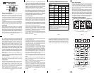
Front Panel DIP-Switch Settings
Fig. 3 Front Panel DIP-Switches
Link Segment/Link Propagate “LS/LP” DIP-Switch
This DIP-Switch controls the Link Propagate or Link
Segment modes. When the DIP-Switch is in the “LS”
position (factory setting), Link Segment mode is enabled.
In the “LP” position, Link Propagate mode is enabled.
Remote Fault Detection “RFD” DIP-Switch
To enable Remote Fault Detection mode, set the “RFD”
DIP-Switch to the “RFD” position.
To enable RFD + LS mode, also set the LS/LP DIP-
Switch to the “LS” position. To enable RFD + LP mode,
set the LS/LP DIP-Switch to the “LP” position.
The RFD DIP-Switch selection is ignored on ports set to
Auto-Negotiation mode.
NOTE: Connecting two converters with both set to RFD
mode is not supported and will cause a “deadly embrace”
lockup.
Symmetrical Fault Detection “SFD” DIP-Switch
To enable Symmetrical Fault Detection mode, set the
“SFD” DIP-Switch to the “SFD” position, the “LS/LP”
DIP-Switch to the “LS” position and the “RFD”
DIP-Switch to the “Off” position.
GX/X SPECIFICATIONS
MOUNTING AND CABLE ATTACHMENT
The iConverter modules are hot-swappable and can
be installed into any chassis in the
iConverter family.
To install the module in a chassis, perform the following
steps:
1. Carefully slide the iConverter module into the
installation slot, aligning the module with the
installation guides. Ensure that the module is firmly
seated against the backplane.
2. Secure the module in the chassis by using the
panel fastener screw (attached to the module).
3. Connect the appropriate multimode or single-mode
fiber cable to a 1000BASE-X Ethernet device.
NOTE: The iConverter transmit (Tx) must attach to the
receive side on other device; the receive (Rx) must
attach to the transmit.
4. When using single-fiber (SF) media converter
models, the Tx wavelength on one end has to match
the Rx wavelength on the other.
NOTE: Based on this guideline, the SF media converter
models must be used in pairs, such as the 8550-01
matched with the 8551-01.
Model Type GX/X
Protocols
1000BASE-SX/LX
Fiber
Connectors
SC, MT-RJ, LC,
Single-Fiber SC
Controls
BP Enable, LS/LP, RFD,
SFD, F/O Auto/Man
LED Displays
Power, FO link, FDX/HDX
Dimensions
W:0.85" x D:4.5" x H:2.8"
Weight
8 oz.
Compliance
UL, CE, FCC Class A
Power
Requirement
2.2A @ 3.3VDC (typical)
Temperature
Standard: 0 to 50º C
Storage: -40 to 80º C
Humidity
5 to 95% (non-condensing)
Altitude
-100m to 4000m
MTBF (hrs)
640,000
It is recommended when connecting two GX/X modules
together to use port 1 as the common port between
modules (or port 1 to port 2).
The GX/X should not be installed in the 1-slot chassis
because of power and heat constraints.