


installed management modules to the RIGHT “SL” position to enable Slave-Only
mode.
SW5, SW6, SW7, SW8 - RESERVED
These DIP-switches are for factory use only and must always remain in the LEFT
position (factory default).
2) INSTALL MODULE IN CHASSIS AND CONNECT CABLES
a. Carefully slide the module into an open slot in the chassis. Align the module with
the installation guides and ensure that the module is firmly seated against the
backplane. Secure the module by fastening the front panel thumbscrew (push in
and turn clockwise to tighten) to the chassis front. Verify the “Pwr” LED is ON
(indicating the chassis is powered).
b. Insert the SFP Fiber transceivers into the Port 1 and Port 2 SFP receptacles on the
2FXM.
NOTE: The release latch of the SFP Fiber transceiver must be in the closed
position before insertion.
d. Connect an appropriate multimode or single-mode fiber cable to the SFP fiber
ports of the installed module. It is important to ensure that the transmit (TX) is
attached to the receive side of the device at the other end and the receive (RX) is
attached to the transmit side. Single-fiber (SF) media converter models operate in
pairs. The TX wavelength must match the RX wavelength at the other end and the
RX wavelength must match the TX wavelength at the other end.
NOTE: In order to support Remote OAM Management Mode, Port 1 of the
2FXM must be connected to the Port 1 on the 2FXM or link partner.
3) CONFIGURE MODULE VIA COMMAND LINE INTERFACE
To access the Command Line Interface (CLI), connect the 2FXM RS-232 Console Port
to the COM port of a computer equipped with terminal emulation software such as
HyperTerminal. The Console Port (DCE) is a mini DIN-6 female connector which can
be changed to a DB-9 connector with the included adapter. The 2FXM Console Port is
a standard asynchronous serial interface.
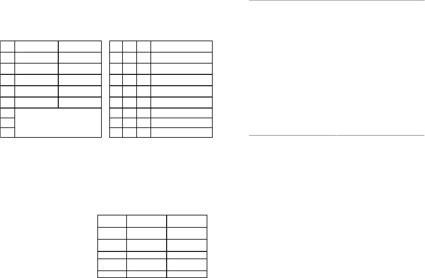
Start HyperTerminal and select the correct COM Port in the HyperTerminal “Connect
To:” window. Set the serial port to the following:
Bits Per Second 57,600
Stop Bits 1
Data Bits 8
Parity NONE
Hardware Flow Control NONE
Once connected, press <ENTER> to bring up a command line prompt on the attached
PC. A new 2FXM module does not have a password, and will skip the Password
Entry screen and go straight to the Management Options screen. If a password has
been set, the Password Entry screen will be displayed. Type the password and press
<ENTER>, the 2FXM will respond with the Management Options screen:
SW3 AND SW4 - RESERVED
These DIP-switches are for factory use only and must always remain in the LEFT
(factory default) position.
SW5 - FIBER PORT 2 FULL/HALF DUPLEX
Setting this DIP-switch to Half-Duplex “HDX” facilitates a connection that supports
Half-Duplex. Setting this DIP-switch to Full-Duplex “FDX” facilitates a connection that
supports Full-Duplex operation.
SW6, SW7, SW8 - LINK MODES
The module supports multiple link modes for fault detection and isolation. Link Segment
should be used for the initial installation of the module. Once installed and operational,
the link mode can be modified.
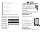
Switch Left
(Factory Default)
Right SW6 SW7 SW8 Link Mode Selection
SW1 Off:
Pause Disable
PAUS:
Pause Enable
Left Left Left Link Segment (LS)
(Factory Default)
SW2 FDX:
Fiber Port 1Full-Duplex
HDX:
Fiber Port 1Half-Duplex
Right Left Left Link Propagate (LP)
SW3
Reserved Reserved
Left Right Left Remote Fault Detect + Link
Segment (RFD + LS)
SW4
Reserved Reserved
Right Right Left Remote Fault Detect + Link
Propagate (RFD + LP)
SW5 FDX:
Fiber Port 2 Full-Duplex
HDX:
Fiber Port 2Half-Duplex
Left Left Right Symmetrical Fault Detect (SFD)
SW6
See Link Mode Selection
Right Left Right Illegal Setting
SW7 Left Right Right Illegal Setting
SW8 Right Right Right Illegal Setting
Figure B: DIP-Switch Bank 1
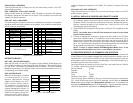
DIP-SWITCH BANK 2
SW1, SW2 - BACKPLANE ENABLE
When the DIP-switch is in the LEFT “DS” position (factory default), the Backplane Port
of the 2FXM is isolated from the chassis’ Ethernet Backplane. When the DIP-switch
is in the RIGHT “EN” position, the Backplane Port is enabled. This allows Ethernet
Backplane connectivity to an adjacent module via the chassis Backplane Link “A” or
“B” depending on the switch setting.
SW4 - MASTER/SLAVE
When the 2FXM module is installed
in a chassis with an
iConverter
Network Management Module
(NMM), set DIP-switch to the LEFT
“M/SL” position (factory default).
The assignment of mastership is
automatically negotiated by the
installed management modules. To
designate the 2FXM module as the
master of the chassis, set the DIP-
switch to the LEFT “M/SL” position,
and set the DIP-switch of the other
Switch Left
(Factory Default)
Right
SW1 A-DS: Disabled
Backplane Port A
A-EN: Enabled
Backplane Port A
SW2 B-DS: Disabled
Backplane Port B
B-EN: Enabled
Backplane Port B
SW3 Reserved Reserved
SW4 M/SL:
Auto Select
SL:
Slave-Mode Only
SW5 - SW8 Reserved Reserved
Figure C: DIP-Switch Bank 2