


iConverter
®
T1/E1 Plugin Module USER MANUAL
The iConverter T1/E1 media converter provides standard T1 (1.544Mbps) or E1
(2.048Mbps) copper to fiber conversion and can be used to extend the demarcation
point between service provider and networking equipment. T1/E1 media converters
operate in pairs, extending distances over fiber, which improves noise immunity, quality
of service, intrusion protection and network
security.
The T1/E1 supports Small Form Pluggable
(SFP) transceivers, enabling adaptability to
different fiber types, distances and
wavelengths, providing maximum flexibility
across a variety of network architectures and
topologies.
INSTALLATION PROCEDURE
1) Configure DIP-Switches
2) Install Module in the Chassis and Connect Cables
3) Verify Operation
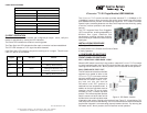
1) CONFIGURE DIP-SWITCHES
FRONT PANEL DIP-SWITCHES
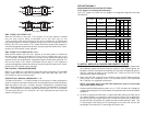
SW1 - LOCAL DUAL LOOP-BACK “LOOP”
When this DIP-switch is set to the “Loop” position, it sets the
iConverter T1/E1 converter
to a dual loop-back mode (see Figure B) on both the fiber and copper connections. By
returning the DIP-switch to the “Norm” position, the unit resumes normal operation.
SW2 - FIBER OPTIC TEST “FOT”
This DIP-switch will allow the entire fiber
segment to be tested at either of the
iConverter T1/E1 converters without
having to set DIP-switches on both units.
When this DIP-switch is set to “FOT”,
the local unit (the unit with the
DIP-switch in the “FOT” position) is
switched into local loop-back mode. In
addition to the local loop-back mode of
operation, the fiber TX port is further
encoded to carry a remote loop-back
protocol. This remote loop-back protocol
sets the remote unit at the other end of
the fiber link to a remote loop-back mode
of operation and returns a signal to the local unit (see Figure C). A fast blinking “Tst”
LED on the local unit and a slow blinking “Tst” LED on the remote unit shows confirmation
that the fiber segment is communicating properly between devices. By returning the
DIP-switch to the “Norm” position, the unit resumes normal operation.
CABLE SPECIFICATIONS:
UTP Cable for T1 and E1
Gauge 22 to 24 AWG
Impedance 100 ohms +/- 10%
Impedance Characteristic 2.6dB/100M @ 1Mhz
Maximum Distance T1 6,000 ft E1 8,000 ft
Coax Cable for E1
Gauge 22 to 24 AWG
Impedance 75 ohms +/- 10%
Impedance Characteristic 2dB/100M @ 1MHz
Maximum Distance 8,000 ft
3) VERIFY OPERATION
Once the module has been installed and configured per steps 1 and 2, verify the
module is operational by viewing the LED indicators.
The Power LED indicates the module is receiving power.
The Fiber Optic link LED indicates the fiber optic connection has been established.
The UTP LED indicates a T1/E1 signal has been detected.
If the Fiber Optic LED is blinking, the port is receiving an all 1s signal. This will occur
if the UTP port is not connected.
LED Function
"Legend"
Color OFF State ON State
Power
"Pwr"
Amber No power Module has power
Fiber Optics
"F/O Lk"
Green No Fiber Link
On: Fiber signal detected
Blinking: All ones received
Test
"Tst"
Green Normal
On: Loop or All ones Test Mode
Blinking: FOT Received - Local
Fast Blinking: FOT Received - Remote
UTP
"UTP Lk"
Green No UTP Link
On: UTP signal detected
Blinking: All ones received
Form 040-08700-002 A 7/08
Omnitron Systems Technology * 140 Technology Dr. #500 * Irvine, CA 92618
949.250.6510 tel * 949.250.6514 fax * www.omnitron-systems.com
Figure A: DIP-Switch Location