


DIP-SWITCH BANK 1
BOARD MOUNTED DIP-SWITCH SETTINGS:
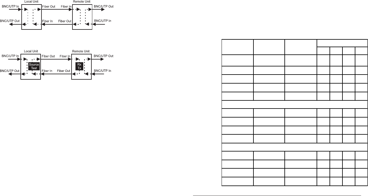
T1/E1 Copper Line Configuration Settings:
The T1/E1 copper line codes and line lengths are configured using board mounted
DIP-switches.
Line Type Port Type Distance
DIP-Switch Position
1234
T1 DSX-1
(default)
RJ-45/48 0' to 133' Down Down Down Down
T1 DSX-1 RJ-45/48 133' to 266' Down Down Down Up
T1 DSX-1 RJ-45/48 266' to 399' Down Down Up Down
T1 DSX-1 RJ-45/48 399' to 533' Down Down Up Up
T1 DSX-1 RJ-45/48 533' to 655' Down Up Down Down
T1 DS1 RJ-45/48 0 dB Down Down Down Down
T1 DS1 RJ-45/48 -7.5 dB Down Up Down Up
T1 DS1 RJ-45/48 -15 dB Down Up Up Down
T1 DS1 RJ-45/48 -22.5 dB Down Up Up Up
E1 75 ohm Coax/BNC Standard Up Down Down Down
E1 120 ohm RJ-45/48 Standard Up Down Down Up
E1 75 ohm Coax/BNC Extended Up Down Up Down
E1 120 ohm RJ-45/48 Extended Up Down Up Up
2) INSTALL MODULE IN CHASSIS AND CONNECT CABLES
a. Carefully slide the module into an open slot in the chassis. Align the module with
the installation guides and ensure that the module is firmly seated against the
backplane. Secure the module by fastening the front panel thumbscrew (push in
and turn clockwise to tighten) to the chassis front. Verify the “Pwr” LED is ON
(indicating the chassis is powered).
b. When using the SFP model (8719-0 or 8739-0), insert the SFP Fiber transceiver
into the Port 1 SFP receptacle on the T1/E1 converter (see the SFP Data Sheet
091-17000-001 for supported transceivers).
NOTE: The release latch of the SFP Fiber transceiver must be in the closed
(up) position before insertion.
c. Connect to the RJ-45/48 connector on the
iConverter T1/E1 converter via a Category 3
or better cable (Category 5 is recommended), and attach the other end to the network
equipment.
d. Connect an appropriate multimode or single-mode fiber cable to the fiber port of
the installed module. It is important to ensure that the transmit (TX) is attached to
the receive side of the device at the other end and the receive (RX) is attached to
the transmit side. Single-fiber (SF) media converter models operate in pairs. The
TX wavelength must match the RX wavelength at the other end and the RX
wavelength must match the TX wavelength at the other end.
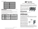
Figure B: Dual Loopback Mode
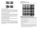
Figure C: Fiber Optic Test Mode
SW3 - FORCE 1S TO FIBER “FO1”
When this DIP-switch is set to the “FO1” position, an “all ones” pattern is inserted
into the data stream being transmitted out of the fiber port on the
T1/E1 converter. Data being received on the coax or twisted pair is disabled and
data being received on the fiber is passed through to the coax or twisted pair side. A
blinking “Tst” LED on the remote T1/E1 shows confirmation that the fiber segment is
communicating properly between the devices. By returning the DIP-switch to the “Norm”
position, the unit resumes normal operation.
SW4 - FORCE 1S TO COAX OR UTP “CU1”
When this DIP-switch is set to the “Cu1” position, an “all ones” pattern is inserted into
the data stream being transmitted out of the coax or twisted pair port on the
T1/E1 converter. Data being received on the fiber will be disabled and data being
received on the coax or twisted pair is passed through to the fiber side. A blinking “Tst”
LED on the remote T1/E1 shows confirmation that the Coax or UTP segment is
communicating properly between the devices. By returning the DIP-switch to the “Norm”
position, the unit resumes normal operation.
SW1 AND SW2 - AMI/B8ZS/HDB3 MODE
B8ZS (T1) or HDB3 (E1) is the default line encoding mode of operation. To select AMI
mode, enable both the Local Dual Loop-back “Loop” and Fiber Optic Test “FOT”
DIP-switches on the front of the module.
PUSH BUTTON - MANUAL CROSSOVER “= / X”
The Manual Crossover “= / X” button located on the front panel is used to eliminate the
need for crossover and custom cables when connecting devices to the RJ-45/48 port.
When the button is in the out “=” position, the port is configured for a straight-through
cable. When the button is in the in “X” position, the port is configured for a crossover
cable. The twisted pair connection requires two active pairs in a T1/E1 environment.
The active pairs are pins 1 & 2 and pins 4 & 5. Only dedicated wire pairs should be
used for the active pins.