


iConverter
®
X21 Plug-in Module USER MANUAL
The Omnitron iConverter
®
X21 is a serial to fiber media converter featuring several
configuration modes enabling connection to a wide variety of X.21 and RS-530
applications. Data rates of up to 8.192Mbps are supported.
The X21 supports standard DCE sourced timing
and terminal timing modes. The included
adapter cable accommodates different
connector gender types. The X21 features local
loopback on the serial and fiber ports to facilitate
testing and installations.
INSTALLATION PROCEDURE
1) Configure DIP-Switches
2) Install Module in the Chassis and Connect Cables
3) Verify Operation
1) CONFIGURE DIP-SWITCHES
FRONT PANEL DIP-SWITCHES
SW1 - DCE/DTE
When this DIP-switch is in the “DCE” (default) position, the serial port is configured to
connect to a DCE device. When the DIP-switch is in the “DTE” position, the serial port
is configured to connect to a DTE device.
SW2 - SET CLOCK (RXC) POLARITY
When this DIP-switch is in the Receive Clock “RC” (default) position, the clock edge
used to sample the data on the serial port is defined by the TIA/EIA-334-C specification.
When the DIP-switch is in the Receive Clock Inverted “Inv” position, the data on the
serial port is sampled on the inverted clock edge.
SW3 - DTE SET CLOCK (TXC)
POLARITY
When Terminal Timing mode is
enabled, this DIP-switch will determine
the clock edge used to transfer data.
When the DIP-switch is in the Terminal
Timing Clock “TTC” (default) position,
the clock edge used to sample the data
on the serial port is defined by the TIA/
EIA-334-C specification. When the
DIP-switch is in the Terminal Timing
Clock Inverted “Inv” position, the data
on the serial port is sampled on the
inverted clock edge.
Form 040-08840-002 A 7/08
Omnitron Systems Technology * 140 Technology Dr. #500 * Irvine, CA 92618
949.250.6510 tel * 949.250.6514 fax * www.omnitron-systems.com
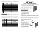
SW1
SW4
Up
Down
Bank 1
SW1
SW4
Up
Down
Front Panel
Figure A: DIP-Switch Location
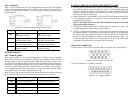
A pinout cross reference table is provided showing the relationship between the serial
port and the X.21 interface. A DE-15 to DB-15 adapter cable is provided.
X.21
DB-15
PIN
Serial
Port
DE-15
PIN
Signal Name
Interchange
Circuit
(AKA)
Direction
Notes
DTE DCE
2
9
11
1
Transmit +
Transmit -
T
(TXD)
IN OUT
3
10
2
7
Control +
Control -
C
(RTS)
IN OUT
4
11
8
12
Receive +
Receive -
R
(RXD)
OUT IN
5
12
13
3
Indication +
Indication -
I
(CTS)
OUT IN
6
13
4
9
Signal Element Timing +
Signal Element Timing -
S
(RXC)
OUT IN
7
14
10
14
DTE Signal Element Timing +
DTE Signal Element Timing -
X
(TXC)
IN OUT
16
Shield Ground
Sheild N/A
Connect to Chassis Ground
815
Signal Ground G
(GND)
N/A Connect to Logic Ground
15 5
N/A Spare Pin
3) VERIFY OPERATION
Once the module has been installed and configured per steps 1 and 2, verify the
module is operational by viewing the LED indicators.
The Power LED indicates the module is receiving power.
The Fiber Optic link LED indicates the fiber optic connection has been established.
Verify the serial port is configured for the correct mode of operation. Check the DCE/
DTE and TD/RD LEDs.
LED Function
"Legend"
Color OFF State ON State
Power
"Pwr"
Green No power Module has power
Fiber Optics
"P1"
Green No Fiber Link
On: Fiber signal detected
Blinking: Activity
Fiber Optics
"Err"
Amber No error detected
Error detected on fiber
(No clock or corrupted messages)
Serial Port
"DCE"
Green Not configured for DCE-facing Configured for connection to a DCE device
Serial Port
"DTE"
Green Not configured for DTE-facing Configured for connection to a DTE device
Timming Mode
"TD/RD"
Green No activity / No clock detected Blinking: Activity
Loopback
"Local LB""
Amber
Loopback/Test mode not
enabled
Blinking: Unit in loopback