


SW4 - LOOPBACK
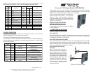
When “L-LB” is selected, the serial port data signals are looped back to the attached
device. At the same time, the fiber port is looped. If the module has Terminal Timing
enabled (see DIP-SWITCH BANK 1), the clock signals are also looped back to the
attached device.
Figure B: Loopback modes showing Terminal Timing
Switch Down Up
SW1 DCE:
DCE Interface enabled
DTE:
DTE Interface enabled
SW2 RC:
RXC Clock polarity normal
Inv:
RXC Clock polarity inverted
SW3 TTC:
TXC Clock polarity normal
Inv:
TXC Clock polarity inverted
SW4 Norm:
Loopback disabled
L-LB:
Loopback enabled
DIP-SWITCH BANK 1
SW1 -TERMINAL TIMING
When this DIP-switch is in the Down (default) position, Terminal Timing is disabled.
When this DIP-switch is in the Up position, Terminal Timing is enabled. When Terminal
Timing disabled, it uses the ‘Signal Element Timing’ clock (SET clock, circuit S, X.21
pin pair 6, 13) as supplied by the DCE device to time Transmit data (TXD) and Receive
data (RXD). This is called Contra-directional Timing. When Terminal Timing is enabled,
it uses ‘DTE Signal Element Timing’ clock (DTE SET clock, circuit X, X.21 pin pair 7,
14) as supplied by the DTE device to time TXD, and uses ‘Signal Element Timing’
clock to time RXD. This is called Co-directional Timing.
When Terminal Timing is used, both the local and remote media converter must be set
to use Terminal Timing, as well as the devices connected to each converter.
Switch Down Up
SW1 Off: Terminal Timing disabled On: Terminal Timing enabled
SW2 Off: Reserved On: Reserved
SW3 Off: Reserved On: Reserved
SW4 Off: Reserved On: Reserved
2) INSTALL MODULE IN CHASSIS AND CONNECT CABLES
a. Carefully slide the module into an open slot in the chassis. Align the module with
the installation guides and ensure that the module is firmly seated against the
backplane. Secure the module by fastening the front panel thumbscrew (push in
and turn clockwise to tighten) to the chassis front. Verify the “Pwr” LED is ON
(indicating the chassis is powered).
b. When using the SFP model (8859-0), insert the SFP Fiber transceiver into the Port
1 SFP receptacle on the X21 converter (see the SFP Data Sheet 091-17000-001
for supported transceivers).
NOTE: The release latch of the SFP Fiber transceiver must be in the closed
(up) position before insertion.
c. Connect the included adapter cable to the serial port on the X21 converter. Use
the appropriate gender plug to attach the X.21 device.
d. Connect an appropriate multimode or single-mode fiber cable to the fiber port of
the installed module. It is important to ensure that the transmit (TX) is attached to
the receive side of the device at the other end and the receive (RX) is attached to
the transmit side. Single-fiber (SF) media converter models operate in pairs. The
TX wavelength must match the RX wavelength at the other end and the RX
wavelength must match the TX wavelength at the other end
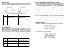
SERIAL PORT CONNECTOR
The serial port is a DE-15 female connector with the following pin-out configuration:
Figure C: Serial Port DE-15 Connector
The X.21 interface is a 2 row DB-15 connector.
Figure D: X.21 DB-15 Interface