


G7/F7/L7/E7 inverter PLC 369
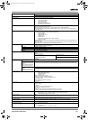
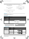
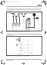
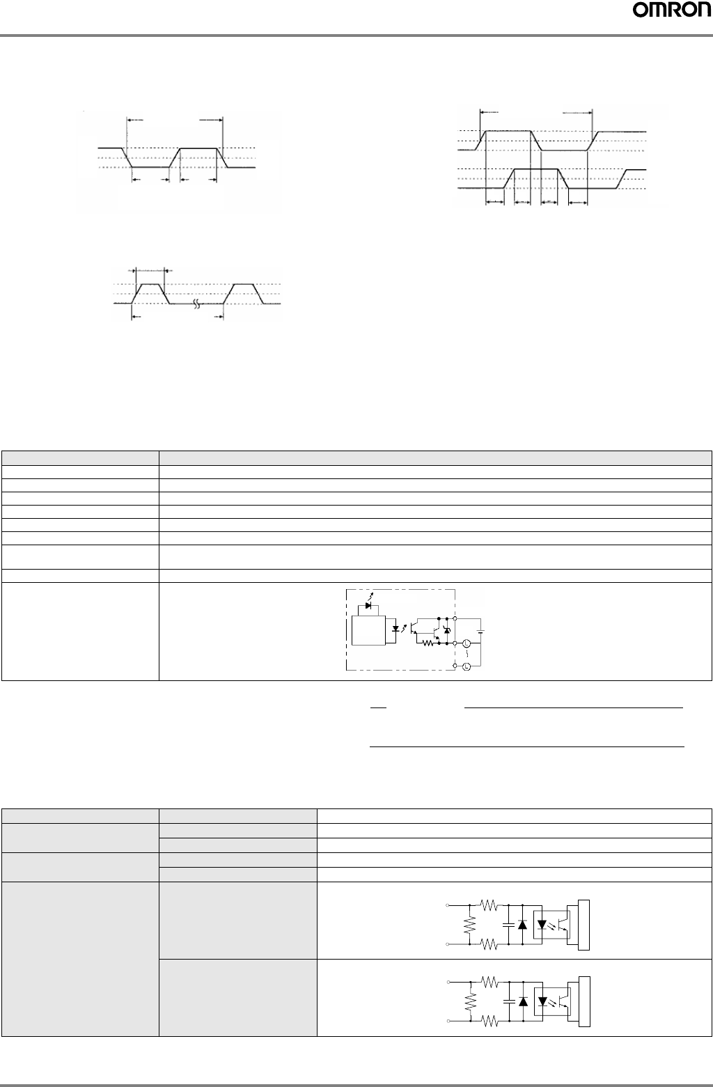
The minimum pulse widths for inputs IN00000 (A-phase input) and IN00001 (B-phase input) are as follows:
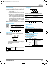
The minimum pulse width for input IN00002 (Z-phase input) is as follows:
Interrupt inputs
3G3RV-P10ST is equipped with inputs that can be used as interrupt inputs (interrupt input mode or counter mode) and quick-response inputs.
The minimum pulse width for these inputs is 50 µs.
Inputs IN 00003 and IN 00004 can be used as interrupt inputs.
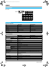
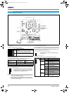
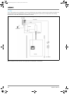
Output specifications
Transistor outputs (sourcing/PNP)
Note: When using OUT 01000 or OUT 01001 as a pulse output, con-
nect a dummy resistor as required to bring the load current
between 0.01 and 0.1 A. If the load current is below 0.1 A, the
ON-to-OFF response time will be longer and high-speed pulses
(source-type transistor outputs) will not be output. If the load cur-
rent is above 0.1 A, the transistor will generate more heat and
components may be damaged.
!Caution
Do not apply voltage in excess of the maximum switching capacity
to an output terminal. It may result in damage to the product or fire.
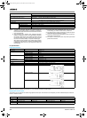
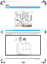
Encoder input specifications
Pulse plus direction input mode,
up/down inputmode, Increment mode
Differential phase mode
Item Specification
Maximum switching capacity 4.5 to 30 VDC, 0.2 A/output
Minimum switching capacity 0.5 mA
Maximum inrush current 0.9 A for 10 ms
Leakage current 0.1 mA
Residual voltage 1.5 V max.
ON response time 20 µs max.
OFF response time 40 µs max. for 4.5 to 26.4 VDC, 10 to 100 mA
0.1 ms max for 4.5 to 30 VDC, 10 to 200 mA
Fuse One fuse per output (cannot be replaced by user)
Circuit configuration
50 µs min.
ON
OFF
12.5 µs
min.
12.5 µs
min.
90%
50%
10%
90%
50%
10%
90%
50%
10%
T
1
T
2
T
3
T
4
100 µs min.
ON
OFF
ON
OFF
Phase A
Phase B
T
1
T
2
T
3
T
4
: 12.5 µs min.
50 µs min.
500 µs min.
ON
OFF
Phase Z
90%
50%
10%
Output LED
Internal
circuits
COM (+)
OUT
OUT
24 VDC
Signal level All
EIA RS-422-A standards
Input impedance A- and B-phase
280 Ω
Z-phase
260 Ω
Response frequency A- and B-phase
50 kHz max.
Z-phase
1 kHz max.
Circuit configuration A- and B-phase
Z-phase
410 Ω
Intrnal circuits
220 pF
330 Ω
330 Ω
A
B
/A
/B
560 Ω
Intrnal circuits
680 pF
180 Ω
180 Ω
Z
/Z
Y203-EN2-02-Katalog.book Seite 369 Mittwoch, 24. Mai 2006 2:22 14