


DATA-LINC GROUPp
LCM100 User’s Guide
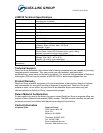
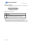
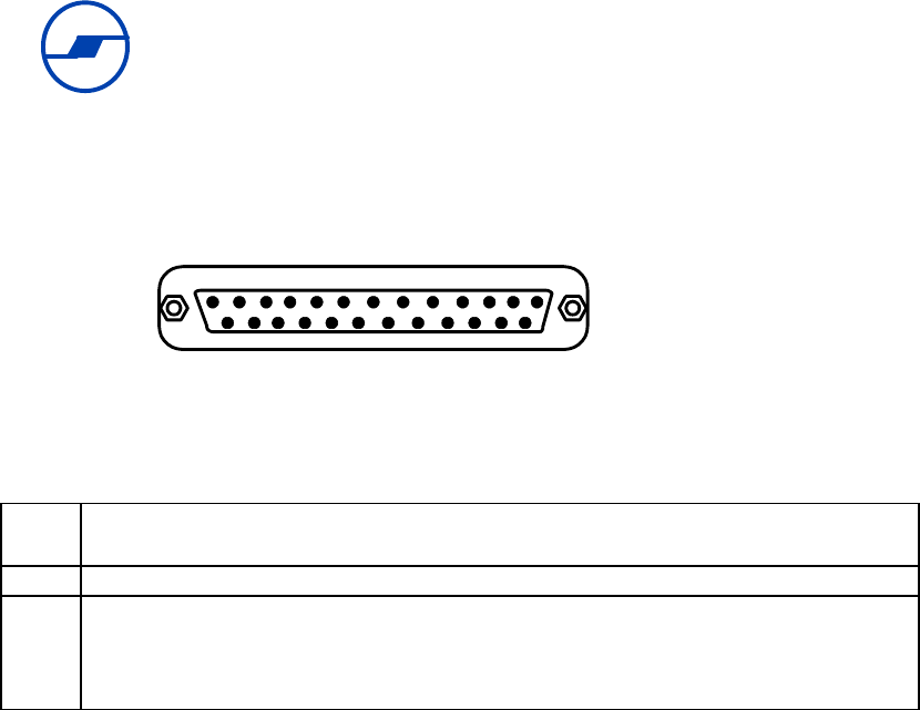
Connector J2 (Female)
Please note that male pin numbering is a mirror image of the female connector depicted below:
13 12 11 10 9 8 7 6 5 4 3 2 1
25 24 23 22 21 20 19 18 17 16 15 14
Figure 3: DB-25P J2 Connector Pins
J2
Pin
Description
9-19 Pins 9-19 are unused, open.
20
Data Terminal Ready
Data Terminal Ready output; indicates that the terminal is on and
operational. This line is enabled, pulled up to +12 volts through a 4.7K ohm
resistor.
Notes
1. On the LCM100-1 module pin 8 is not carried at the connector through P3 because most
computers provide this signal. Pin 8 may be carried to the connector, if desired.
2. On the LM100-2 module, the carrier detect signal is available at the connector because the
interconnected equipment is receiving a signal. Pin 8 may be disconnected at P3, if desired.
PN 161-09998-001A
7