35
Switch Settings Section 3-4
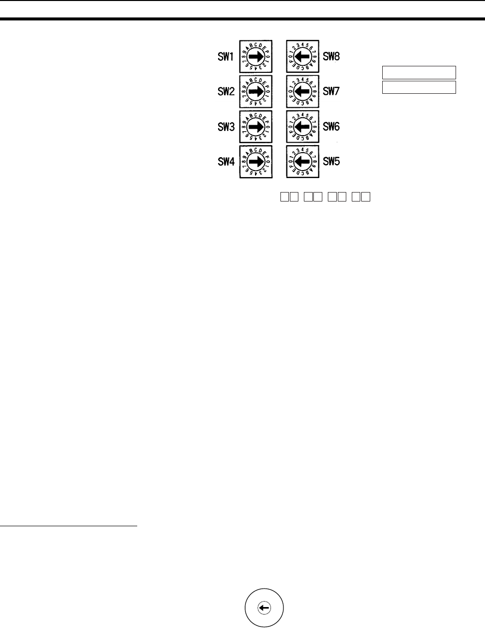
The switches are all factory-set to 0 (00.00.00.00). The Ethernet Unit cannot
be used with this setting; a proper IP address must be set. The following set-
tings cannot be made for the IP address, or the ERC indicator will flash.
All bits in the network number field set to 0 or 1.
All bits in the host number field set to 0 or 1.
All bits in the subnet number field set to 1.
The beginning of the IP address set to 127 (7F Hex)
Example: 127.35.21.16
Note 1. When using the automatic generation method for address conversion, set
switches 7 and 8 to the same values as the node number setting, and set
the rest of the host number to zeroes. For details regarding the host num-
ber, refer to 1-7 IP Addresses. The value for the host number field in the IP
address must match the value for the node number or the ERC indicator
will flash.
2. If a subnet mask is to be set, use the CX-Programmer to set it in the CPU
Bus Unit System Setup. For details, refer to 4-2 CPU Bus Unit System Set-
up.
3-4-2 CJ-series Ethernet Units
Note With CJ-series Ethernet Units, the local IP address is set with the Program-
ming Device for the PC, such as CX-Programmer. For details, refer to 4-2
CPU Bus Unit System Setup and 4-4 DM Area Allocations.
Setting the Unit Number
The unit number is used to identify individual CPU Bus Units when more than
one CPU Bus Unit is mounted to the same PC. Use a small screwdriver to
make the setting, taking care not to damage the rotary switch. The unit num-
ber is factory-set to 0.
Note 1. Turn OFF the power supply before setting the unit number.
2. If the unit number is being set for the first time or changed, then an I/O table
must be created for the PC.
Local IP Address Switch No.
Setting range:
0 to F
1
2 . 3 4 . 5 6 . 7 8 .
0
1
2
3
4
5
6
7
8
9
A
B
C
D
E
F
UNIT
No.
Setting range:
0 to F


