


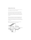

WIRING INSTRUCTIONS
Wire the relay coil from the AUX positive and negative connections of
your OutBack product according to the diagram.
The coil connections (A1 and A2) are not polarity sensitive and the
LED will light in either polarity as long as proper voltage is present.
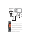
(Required voltage is nominally 12 VDC, with a minimum of 9 volts.) If
you are unsure, run the AUX positive wire to the A2 terminal and the
AUX negative wire to the A1 terminal, twisting the wires together for a
clean look.
Wire your two-wire gen start connections from the generator to the
normally open and common connections of the relay module. One
wire from the generator will go to the common (COM) connection
and the other wire of the generator will go to the normally open (NO)
connection. The side of the relay base has a schematic of the relay and
its connections.
NOTE: Use proper wire size for the current you intend the relay to
handle and and install a fuse or breaker if necessary.
DIN Rail