


8
Common Wiring Con gurations
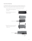
Single FX Series Inverter/Charger and OutBack Controller
• Plug the FX into Port 1 of the HUB.
• The Charge Controller and any future OutBack devices can be plugged into any
remaining non-MATE ports.
Multiple OutBack Charge Controllers Only
• Plug one Charge Controller into Port 1 and the others into any remaining ports.
• A FLEXnet DC can be plugged into a remaining port as well.
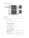
Series/Parallel Phase-Stacked FX Series Inverter/Chargers
• The FX designated as the Master must be plugged into Port 1.
• Plug additional FXs in remaining ports in numerical order followed by any OutBack Charge
Controllers.
• Some PC monitoring software requires that 120/240 VAC series-stacked or series
parallel stacked FX Systems be wired with all LEG 1 (L1) phased FXs as odd numbered
Ports and all LEG 2 (L2) phased FXs as even numbered Ports. This arrangement
also makes programming the FX Slave power save level settings more intuitive.
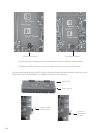
Three- Phase FX Series Inverter/Charger Stacking
• Connect the Master FX (Phase A) to Port 1.
• Connect the phase B Slave to Port 2.
• Connect the phase C Slave to Port 3.
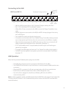
• The HUB jumper must be in the three phase position as described in the three- phase
stacking section (please see next page).
• Other OutBack devices can be plugged into any unused ports. Currently, only three
inverters can be con gured in a three-phase arrangement, but additional non-stacked
inverters—all of which must be Masters—can be plugged into any of the unused ports of
the HUB.
• These non-stacked inverters can only power loads that are independent of the three-phase
loads; additional AC load panels will be required.