


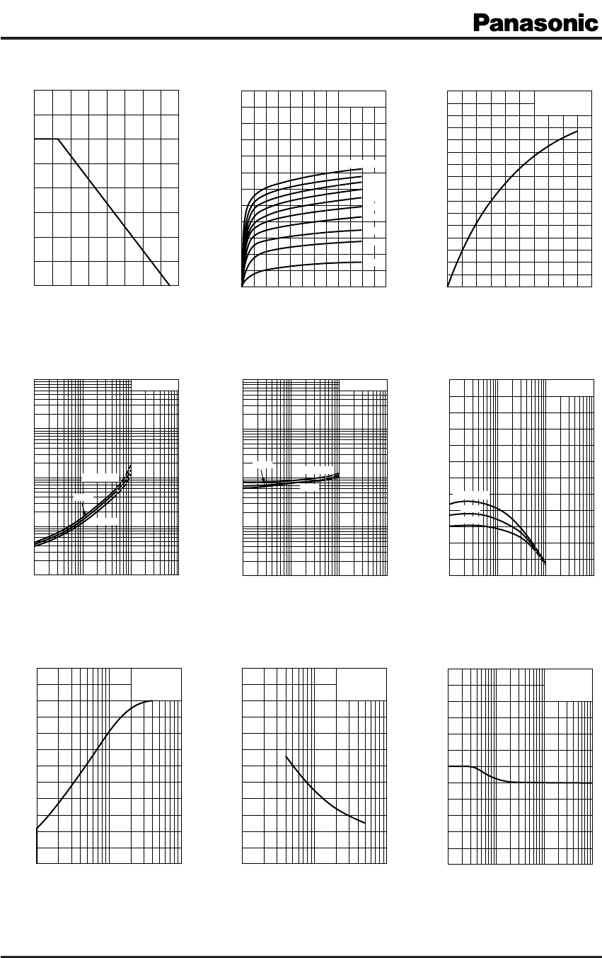
2SB1321A
2
SJC00079BED
V
CE(sat)
I
C
V
BE(sat)
I
C
h
FE
I
C
P
C
T
a
I
C
V
CE
I
C
I
B
f
T
I
E
C
ob
V
CB
V
CER
R
BE
0
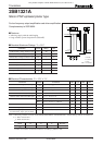
0 16040 12080
200
600
400
800
Ambient temperature T
a
(
°C
)
Collector power dissipation P
C
(
mW
)
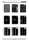
0 –12–2 –10–4 –8–6
0
−1.2
−1.0
−
0.8
−
0.6
−
0.4
−
0.2
−9 mA
−8 mA
−7 mA
−6 mA
−5 mA
−4 mA
−3 mA
−2 mA
−1 mA
I
B
= −10 mA
Collector-emitter voltage V
CE
(
V
)
Collector current I
C
(
A
)
T
a
= 25°C
0 −10−8−6−4−2
0
−
0.8
−
0.6
−
0.2
−
0.5
−
0.7
−
0.4
−
0.1
−
0.3
Base current I
B
(
mA
)
Collector current I
C
(
A
)
V
CE
= −10 V
T
a
= 25°C
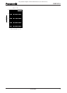
−1
−10
−100
−1 −10
T
a
= 75°C
25°C
−25°C
Collector-emitter saturation voltage V
CE(sat)
(
V
)
Collector current I
C
(
A
)
I
C
/ I
B
= 10
− 0.01
− 0.01
− 0.1
− 0.1
−1
−10
−100
−1 −10
T
a
= −25°C
75°C
25°C
− 0.01
− 0.1
Base-emitter saturation voltage V
BE(sat)
(
V
)
Collector current I
C
(
A
)
I
C
/ I
B
= 10
− 0.01
− 0.1
0
600
500
400
300
200
100
−1 −10
T
a
= 75°C
25°C
−25°C
Forward current transfer ratio h
FE
V
CE
= −10 V
− 0.01
− 0.1
Collector current I
C
(
A
)
1 10 100
0
240
200
160
120
80
40
Transition frequency f
T
(
MHz
)
Emitter current I
E
(
mA
)
V
CB
= −10 V
T
a
= 25°C
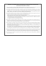
0
−1
24
20
16
12
8
4
−10 −100
Collector-base voltage V
CB
(
V
)
I
E
= 0
f = 1 MHz
T
a
= 25°C
Collector output capacitance
(Common base, input open circuited)
C
ob
(pF)
1 10 100 1
000
0
−120
−100
−80
−60
−40
−20
Base-emitter resistance R
BE
(
kΩ
)
I
C
= −2 mA
T
a
= 25°C
Collector-emitter voltage
(Resistor between B and E)
V
CER
(V)
This product complies with the RoHS Directive (EU 2002/95/EC).