


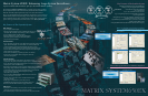
A Rich Array of Features for More Reliable and Efficient Surveillance
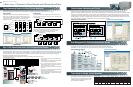
Three Sequencing Features for More Efficient Monitoring
These features allow you to determine the sequence in which you seem images from multiple cameras.
System Controller buttons make monitoring more efficient by enabling instant selection of the pattern of your choice.
Tour Sequence
Automatically switches camera images sequentially on the selected
monitor. Up to 128 patterns can be programmed with as many as 64
steps per pattern. Camera preset position (1 ~ 255) and AUX output (1,
2) can also be controlled and up to 86,339 seconds dwell time is
available in each step.
Group Preset
Allows instant spot display of selected camera with preset position (1 ~
255) on up to 64 pre-selected monitors at once. Up to 128 patterns can
be programmed.
step 1
Tour 1
C1
Tour 2
C5
Tour 3
C9
Tour 128
C13
step 2
C2
C6
C10
C14
step 3
C3
C7
C11
C15
step 64
C16
C4
C8
C12
The image shifts automatically from one camera to another, as programmed.
The images can be
seen on any monitor.
M1 M64
Alarm ID Priority
Alarm Source Alarm Output
Action
No. Type ID Preset AUX
Dwell Time
Text Target
0Camera spot 1 1 1 3sec Entrance 1 Zoom 1 (M1, M2)
1Camera spot 2 – OFF 5sec Entrance 1 Wide 1 (M1, M2)
256 1 Terminal 513 2 Tour SEQ 1 – – 3sec Entrance Area 2 (M11, M12)
8Group SEQ 1 – – 4 sec Group level 1
3 (M31, M32, M33,M34)
9 Text only – – – –
Entrance 1 Level 1
16 (M63, M64)
Alarm Output 513
Action 0
Camera 1
Target 1 M1
Action 1
Camera 2
Target 1 M2
Action 2
Tour SEQ1
Target 2 M11
C1
M11 M11 M11
Action 8
Group SEQ1
Target 3 M31, 32, 33, 34
Action 9
Text
Target 16 M63
Entrance 1
Level 1
Camera 1
Camera 2
Preset Position 1
(Zoom in to Entrance 1)
Te rm inal
Alarm 256
Example: Terminal Alarm Event No.256
Sensor
System
Entrance 1
Infrared
Sensor
WJ-SX650
ZOOM
Sensor
C2 C3
C1
M31
C20
M32
C5
M33
C15
M34
The Matrix System650EX supports flexible alarm handling, up to 1,024 alarm programs and various alarm interfaces including
1,024 terminal inputs, 256 terminal outputs, 512 camera alarms, 512 Video loss alarms and 1,024 serial alarm inputs (Total of terminal
inputs and outputs is 1,024). An alarm program can activate up to 10 actions including camera spot, Tour Sequence, Group Sequence
and Text. Each action can be assigned to one of the 16 targets, which includes up to 64 monitors, so that the multiple actions can
effectively be displayed across the alarm target monitors.
An alarm terminal output can be triggered when an alarm is activated, acknowledged or reset.
Group Sequence 1
Monitor 1
step 64
step 1
C1
Group Sequence 2
Group Sequence 128
Monitor 2
C20
Monitor 3
C5
Monitor 64
C15
Group Sequence
Automatically switches Group preset patterns sequentially. Up to 128
patterns can be programmed with as many as 64 steps per pattern.
Up to 86,339 seconds dwell time is available in each step.
Group Preset 1
Monitor 1 Monitor 2 Monitor 3 Monitor 64
Group Preset 2
Group Preset 128
C1 C20 C5 C15
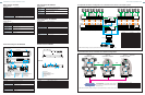
• Alarms can be scheduled by programming the timer
event function.
• Alarm priority control enables effective management
for alarms, timer events and operators.
• Up to 1,024 Alarm Program status, up to 100 events
of Alarm History and up to 100 events of Video-loss
History can be viewed on a monitor.
• Up to 30 days of Alarm logs can be stored in the main
CPU unit.
• Alarms can be suspended individually by Arm/Disarm
button from the system controller.
• Hold mode displays first alarm while sequence mode
displays multiple alarms sequentially when multiple
alarms are activated.
Up to 512 operators can be registered with individual operator IDs, passwords and priority (0 to 65,534). 16 operator levels are fully
configurable with numerous parameters such as camera select, alarm select and DVR select.
Administrators for the system setup are registered separately, allowing secure user management.
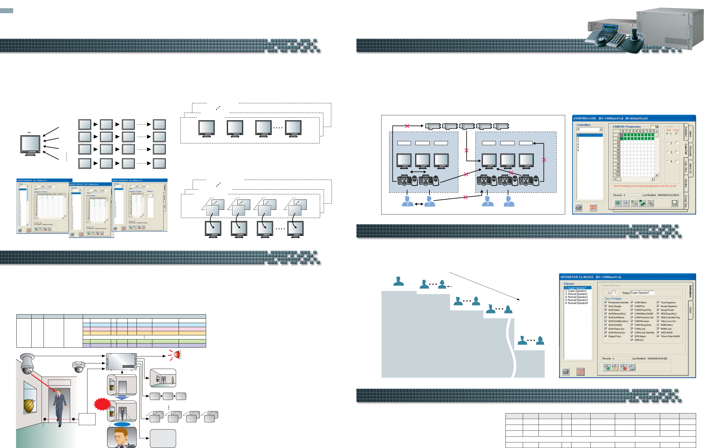
The System650EX has flexible system partitioning and priority features allowing for advanced operation management.
Partitioning includes Controller to Area, Monitor, Camera view, Camera control, Group Sequence, Alarm, Alarm I/O, Recorder,
Operator-to-Controller and Monitor-to-Camera. Priority control includes Operator, Controller, Alarm and Timer-event so that the flexible
priority control is available. For example, a higher operator will not be bothered by the lower priority alarms or timer events and higher
priority alarms will not be disturbed by the lower priority operators or timer events. In addition, the System650EX can create the Areas
including Monitors, Controllers, Tour Sequences, Group Presets and Group Sequences. All these items, except controllers, can have a
local number enabling the operators to select them by using a simpler reference number.
4 5
Event ID Priority Action ID Monitor Start Date Start Time End Date End Time Repeat
15Alarm Disarm – – 11 Nov. 2006 08:00 – – Daily
25Alarm Arm – – 11 Nov. 2006 17:00 – – Daily
310Camera spot 1 1 11 Nov. 2006 08:00 31 Jan. 2007 17:00 Weekly
1,024 20 Tour SEQ 3 4 1 Dec. 2006 09:00 1 Dec. 2006 18:00 Once
•
•
•
MAJOR FUNCTIONS
Controller 1
ID 1-5
Local 1-5
Local -1
Physical 11
Tour
Controller 2
Controller priority
Operator priority
Operator to Controller
Controller-Camera
Logical 1
Area
Cam-Mon
AREA 1
ID 1-5
Local 1-5
Local -2
Physical 12
G-Preset
ID 1-5
Local 1-5
Local -3
Physical 13
G-SEQ
Controller 3
ID 6-10
Local 1-5
Local -1
Physical 14
Tour
Controller 4 Controller 5
Controller-Mon
Cont-G.SEQ
AREA 2
ID 6-10
Local 1-5
Local -2
Physical 15
G-Preset
ID 6-10
Local 1-5
Local -3
Physical 16
G-SEQ
Logical 2 Logical 3 Logical 4 Logical 5
Up to 1,024 Alarm Events Ensure That You Capture Vital Scenes
Flexible System Partitioning and Priority
User Management for Preventing Unauthorized Access
Camera spot, Tour Sequence, Group Preset,
Group Sequence, Alarm arm/disarm and Mode
change features can automatically be activated,
following programmed schedules. Up to 1,024
timer events can be registered.
Timer Events for Simple, Certain Operation
Level 2
Level 1
Priority
OPERATOR’S LEVEL TABLE
OPE
2
OPE
6
Password
21233
OPE
1
12123
22342
Permission Override
Area Change
ALM Select
ALM Reset (ALL)
ALM Ack/Reset
ALM Arm/Dis (ALL)
ALM Arm/Dis
ALM Status Svc
ALM History Svc
Output Ports
CAM Select
CAM Pos
CAM Preset Prg
CAM Menu On/Off
CAM Function Cds
CAM Receiver
CAM Setup Data
CAM Lock
CAM Lock Override
DVR Select
DVR Ctrl
Tour Sequence
Group Sequence
Group Preset
SEQ Stop (ALL)
SEQ Controller Prg
Video Loss Svc
MON Select
MON Lock
OSD On/Off
Time & Date On/Off
Area Change
ALM Reset (ALL)
ALM Ack/Reset
ALM Arm/Dis
ALM Status Svc
Output Ports
CAM Select
CAM Pos
CAM Menu On/Off
CAM Function Cds
CAM Receiver
CAM Lock
CAM Lock Override
Group Sequence
Group Preset
SEQ Stop (ALL)
Video Loss Svc
MON Select
Time & Date On/Off
ALM Status Svc
CAM Select
CAM Pos
CAM Receiver
CAM Lock
Group Sequence
Group Preset
SEQ Stop (ALL)
MON Select
Time & Date On/Off
CAM Select
CAM Lock
Group Sequence
SEQ Stop (ALL)
Time & Date On/Off
Group Sequence
SEQ Stop (ALL)
Time & Date On/Off
Level 3
OPE
7
OPE
16
31256
34682
Level 4
OPE
17
OPE
35
34397
31625
Level 16
OPE
500
OPE
512
39262
33681
Operator Registration Example
Operator Classes Setup Menu
Setup Example
Controller-Camera Partition Setup Menu
Partitioning and Priority Overview
Tour Sequences Setup Menu
Group Presets Setup Menu
Group Sequences Setup Menu