


AB5
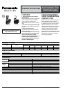
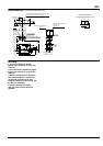
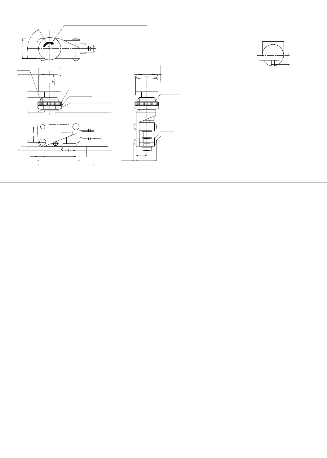
DIMENSIONS (mm) (General tolerance: ±0.4)
NOTES
Arrow to indicate rotation direction and ON indication
printed at top of push-button on lock types.
13.5
7.15
8.5
11.5
Keyway
R50
15 dia.
20.0
10
0.5
3.6
3.0
3.8
38.8
(22.2)
28.8
(10.3)
3.4
0.5
22.8
2
NC
C
1
C
NO
3
Lock nut (15 dia.)
Spring washer
Hex nut (opposing sides: 14)
26.2
±0.5
47.4
±0.4
51.0
±0.8
Movement until operation (P.T.)
1.6max
Full stroke during operation
Push type: 2.4
Lock type: 2.0
7.15
M12 P=1.0
2 fibers
2 rivets
14max1.6max
Lock rotation
angle 60°
Mounting dimensions
(Panel thickness: Max. 3 mm)
1.7
±0.1
12.2
±0.1
5.2
±0.1
1. For panel installation, please
tighten with a torque of no more than
1.47 N·m.
2. For push-button installation, please
tighten with a torque of no more than
0.49 N·m.
3. Notch is provided on the operation
shaft and pushbutton to prevent the
push-button from falling off. After
using the notch, screw in a further 120
to 160° (3 or 4 threads).
4. Please note that the number
changes when the push-button is
replaced.
All Rights Reserved © COPYRIGHT Matsushita Electric Works, Ltd.