


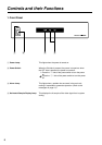
15
Restrictions
Reference vs. Input Signal Phase
The 2K processor does not have input buffer memory;
therefore, be sure to lock and match the phase between
the reference signal and input signals. If the signal
phases are not locked and matched, the phase of
signals, output signals might be corrupted.
System vs. Input Signal Frequency
The 2K processor does not have input buffer memory;
therefore, be sure to match the frequencies between the
system settings and input signals. If the frequencies are
not matched, output signals might be corrupted.
4:2:2 (Y Pb Pr) Output
The 2K Processor has no built-in gamma conversion.
Therefore, in the output of 4:2:2 (YPbPr color space),
only conversion from RGB (gamma = 2.2) produces
the correct hue. The hue varies in other cases.
Video Output in SEARCH and FF/REW
Video output in SEARCH and FF/REW is with low-
resolution images, with low image quality.
SYSTEM setting for RGB and XYZ color
spaces
The input of color space signals that differ from those
in SYSTEM results in incorrect color space output.
Playback of recording color space signals on tapes
that differ from those in SYSTEM results in incorrect
color space output.
SYSTEM settings for 2048 and 1920
horizontal samples
Recording and playback depend on the SYSTEM
settings.
zRecording is based on the number of horizontal
samples in SYSTEM settings and Tape ID, even
when different input signals from those in SYSTEM
are supplied.
zPlayback is based on the number of horizontal
samples in SYSTEM settings, even when tape with
a different number of horizontal samples from
those in SYSTEM is played back.
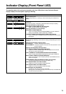
In the above case, FRONT LED (2048/1920) blinks
according to SYSTEM settings.
In addition, when a format other than that supporting
the 2K processor is played back, it blinks rapidly
according to the SYSTEM settings.
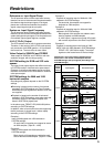
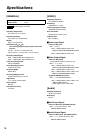
Example 1:
Input of 2048 signals with 1920 selected in
SYSTEM settings:
On each side, 64 samples are cropped to record
as 1920 samples. (Tape ID = 1920)
Example 2:
Input of 1920 signals with 2048 selected in
SYSTEM settings:
Black signals of 64 samples are added to each
side to record as 2048 samples. (Tape ID = 2048)
Example 3:
Playback of recording tape for 2048 with 1920
selected in SYSTEM settings:
On each side, 64 samples are cropped for
playback as 1920 samples.
Example 4:
Playback of recording tape for 1920 with 2048
selected in SYSTEM settings:
Black signals of 64 samples are added to each
side for playback as 2048 samples.
In 4:2:2 output, it appears as normal HD signals
with normal output due to the Side Crop function.
Example 5:
Playback of recording tape in the format of 1080/
23PsF 4:2:2 with 1920 selected in SYSTEM settings:
FRONT LED “1920” blinks rapidly. The output
signals are the freeze frame of the last image.
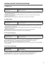
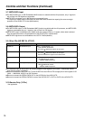
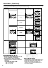
Differences in the actual image conditions due to
differences in the number of H Samples between
SYSTEM settings and input signals (According to the
SYSTEM settings)
SYSTEM
settings
(MENU
selection)
Input signals Recorded images
2048
2048
1920
1920
2048
1920
1920
2048
1920
2048
1920
64 64
1920
2048
1920
2048
64 64
1920
1920 1920