19
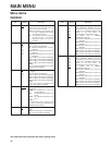
Item Setting Description
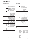
GPI1-8 UNDEF
MARKER1 ON/OFF
MARKER2 ON/OFF
MARKER BACK HALF
MARKER BACK BLACK
CENTER MARKER
INPUT SEL. SDI1
INPUT SEL. SDI2
INPUT SEL. VIDEO
INPUT SEL. YPBPR/RGB
SD ASPECT
HD ZOOM
BACKLIGHT MIN.
R.TALLY
G.TALLY
MONO ON/OFF
GAMMA SELECT
WFM ON/OFF
For allocating particular
functions to particular pins
when remote control
operations are to be
performed using the GPI
signals. For details, refer to
“REMOTE specifications”
(page 22).
GPI
MAIN MENU
The underlined setting indicates the factory setting mode.
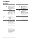
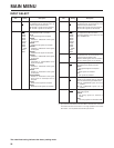
Item Setting Description
BACKLIGHT 0
:
60
For adjusting the backlight brightness to a
level from 0 to 60. The higher the setting,
the brighter the backlight.
FUNCTION WFM
ON/OFF
HV DELAY
UNDEF
For setting the function to be allocated to
the FUNCTION/ENTER button.
WFM ON/OFF
: The Y signal (luminance)
waveforms are displayed.
HV DELAY: The blanked parts of the
images are displayed.
UNDEF: No function is allocated.
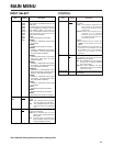
WFM FUNCTION
GPI
For selecting whether the Y signal
(luminance) waveforms are to be displayed
using the FUNCTION/ENTER button or
from the GPI connector.
FUNCTION
: The waveforms are displayed
using the FUNCTION/ENTER
button.
GPI: The operations are performed
from the GPI connector. For
details, refer to “REMOTE
specifications” (page 22).
HD ZOOM FRONT
GPI
For selecting whether the HD ZOOM
function is to be operated using the HD
ZOOM/X button or from the GPI connector.
FRONT
: The function is operated using the
HD ZOOM/X button.
GPI
: The operations are performed from
the GPI connector. For details,
refer to “REMOTE specifications”
(page 22).
PEAKING/ PHASE PEAKING
PHASE
For selecting the PEAKING or PHASE
function for the image control.
PEAKING
: The PEAKING function is
allocated to the control.
PHASE: The PHASE function is allocated
to the control.
USER MODE
LOAD
USER5
USER4
USER3
USER2
USER1
FACTORY
For calling the file in which the user data is
stored.
USER1-5
: These are the files in which the
user has stored data. If the user
data has not yet been stored,
the settings are the same as the
ones in the FACTORY file.
FACTORY
: This file contains the factory
settings.
USER MODE SAVE USER5
USER4
USER3
USER2
USER1
For saving the user data.
SYSTEM CONFIG
Item Setting Description
BATTERY REMAIN OFF
ON
For selecting whether to display the
remaining battery charge.
OFF:
The remaining charge is not displayed.
ON:
The remaining charge is displayed.
STATUS DISPLAY CONTINUE
3SEC. OFF
OFF
For setting how long the status display is to
remain on the screen.
CONTINUE
: The status display appears
continuously at all times.
3SEC.OFF
: The status display appears for
three seconds.
OFF
: The status display does not appear.
CRCC MESSAGE OFF
ON
For selecting whether a message is to be
displayed when a CRCC error has been
detected.
OFF:
A CRCC error message is not displayed.
ON:
A CRCC error message is displayed.
MENU POSITION LT
CENTER
LB
RB
RT
For setting the menu display position.
LT:
The menu is displayed at the top left.
CENTER:
The menu is displayed in the center.
LB:
The menu is displayed at the bottom left.
RB:
The menu is displayed at the bottom right.
RT:
The menu is displayed at the top right.
STATUS POSITION LT
CENTER
LB
RB
RT
For setting the status display position.
LT:
The menu is displayed at the top left.
CENTER:
The menu is displayed in the center.
LB:
The menu is displayed at the bottom left.
RB:
The menu is displayed at the bottom right.
RT:
The menu is displayed at the top right.
ROTARY
POSITION
LB
CB
RB
RT
LT
CENTER
OFF
For setting the display position of the
settings when images have been adjusted
using the image controls.
LB:
T
he settings are displayed at the
bottom left.
CB:
The settings are displayed below the center.
RB:
T
he settings are displayed at the
bottom right.
RT:
The settings are displayed at the top right.
LT:
The settings are displayed at the top left.
CENTER:
The settings are displayed in the center.
OFF:
T
he settings are not displayed.
OSD CONFIG


