


Connectors for industrial equipment
DIN CONNECTORS (AXD)
INTRODUCTION OF OTHER TYPES
2. FEATURES AND CONSTRUCTION OF DIN CONNECTOR WITH HIGHER FUNCTION
1. FEATURES OF REVERSE TYPE DIN
CONNECTOR
New series of reverse types popular in
the U.S.A.
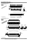
1) Shock resistant socket construction
Integrated construction of the flange and
housing prevent damage to the terminals
from shock.
2) Box-shaped header provides excellent
electrical performance
Box-shaped headers feature long
insulation distance between the
connector and mounting panel and low
capacitance.
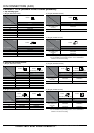
Body
Contact
Flange
OPEN type
Former product
BOX type
Mounting panel
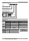
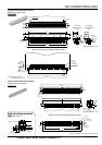
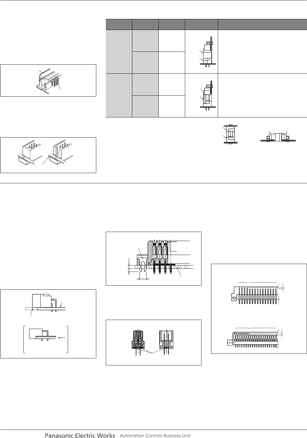
Standard type and reverse type
Types
Header/
socket
Ter minal
shape
Form
Standard
type
Header Angle
The contacts of the socket mounted on the
mother board (power supply side) are covered
to prevent electrical shock and entry of foreign
matter.
Socket Straight
Reverse
type
Header Straight
1. Reduction of total cost
Since the cost of the header is low, it is more
economical to use the header for mother
boards which require multiple pins for
expansion.
2. Matches the designer's requirements for
maximum simplicity in the mother board design.
Socket Angle
The header and socket for the standard
type and reverse type fit each other,
this permits the connections shown in
the figure on the right.
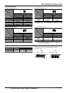
Stacking connection Horizontal connection
Srandard
header
Standard
socket
Reverse
header
Reverse
socket
Standard
socket
Reverse
header
Reverse
socket
Srandard
header
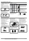
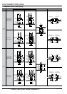
DIN connector enhancement products
which support user circuit designs and
solve problems that occur during
connector mounting.
• PC board top mounting type
• Self-clinching bracket (with temporary
fastening function)
• Flux resistant construction
• Time difference contacts
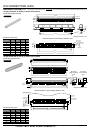
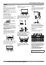
1) PC board top mounting type
• Prevents the entry of flux during
automatic soldering.
• Large position tolerance when mounting
the connector to the PC board permits
the use of automatic mounting.
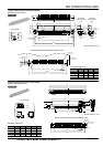
2) Self-clinching brackets
(with temporary function)
• Prevents the connector from shifting
due to vibration and shock.
• Uses the same mounting hole as the
mounting screw.
3) Flux resistant construction
The terminals are sealed with resin to
prevent seepage of flux through the
terminals or entry of flux from the bottom
of the connector.
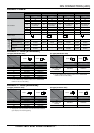
4) Time difference contacts
• ICs are protected from damage at
connection even if the PC board is
inserted or removed without power
connected during maintenance or
inspection. This simplifies circuit design.
•A contact time difference of 1mm for
headers and 1.2mm for sockets is
obrained.
• Time difference contacts can be
arranged as desired.
PC board
Snap off at the notches
after soldering
PC board edge
mounting type
(DIN connector)
mm
Self-clinching bracket
PC board
PC board
mounting hole
2.8±0.05 dia.
1.6
1.4
Sealed
with
resin
Cross section
HeaderSocket
Header
Socket
Standard
contacts
Time difference
contacts
1mm
1.2mm
Standard
contacts
Time difference
contacts
panasonic-electric-works.net/ac