


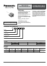
EJ (AEJ)
2. Specifications
Notes: *1 This value can change due to the switching frequency, environmental conditions and desired reliability level, therefore it is recommended to check this with the
actual load.
*2 The upper operation ambient temperature limit is the maximum temperature that can satisfy the coil temperature rise value.
Refer to 6. Conditions for operation, transport and storage mentioned in AMBIENT ENVIRONMENT .
*3 Condition: Nominal switching 100cycles, each cut off 800A
*4 When using a surge absorbing element for the relay coil drive circuit, please use with a surge absorbing element with a clamp voltage of 1.5 to 2.0 times the rated
operating voltage. When the coil is connected in parallel with a diode, resistor or capacitor, the release time will delay which might lead to degradation in shutoff
performance and electrical life.Contact terminals have polarity; therefore, please obey the wiring diagram when connecting contacts.The electrical load
performance value applies when a varistor is connected in parallel with the coil.
REFERENCE DATA
Characteristics Item Specifications
Rating
Arrangement 1 Form A
Contact voltage drop (Initial) Max. 0.15V (at 100A)
Contact material AgCuO type
Nominal switching capacity (resistive load) 100A 100V DC
Max. carrying current/short time carrying current 1,000A (0.1s)
Min. switching capacity (Reference value)*
1
1A 12V DC
Max. cut-off current 800A 100V DC/3 cycle*
3
Overload opening rating 300A 150V DC/10 cycle
Electrical
characteristics
Insulation resistance (Initial)
Min. 100MΩ (at 500V DC)
Measurement at same location as “Initial breakdown voltage” section.
Breakdown voltage
(Initial)
Between open contacts 1,500 Vrms for 1min. (Detection current: 10mA.)
Between contact and coil 2,500 Vrms for 1min. (Detection current: 10mA.)
Operate time (at 20°C 68°F) Max. 30ms (Nominal voltage applied to the coil, excluding contact bounce time)
Release time (at 20°C 68°F) Max. 15ms (Nominal voltage applied to the coil)
Mechanical
characteristics
Shock resistance
Functional
Min. 500 m/s
2
(Nominal voltage applied to the coil)
Min. 50 m/s
2
(deenergized) (Half-wave pulse of sine wave: 11 ms; detection time: 10µs.)
Destructive
Min. 1000 m/s
2
(Nominal voltage applied to the coil or deenergized.)
(Half-wave pulse of sine wave: 6 ms)
Vibration resistance
Functional 10 to 200Hz, 44.1m/s
2
(Nominal voltage applied to the coil or deenergized)
Destructive
10 to 200Hz, 44.1m/s
2
(Nominal voltage applied to the coil or deenergized)
(Time of vibration for each direction; X, Y, Z direction: 4 hours)
Expected life
Mechanical Min. 10
6
Electrical
Min. 10
4
(at 100A 100V DC)
(Resistive load, operating frequency 1s ON, 9s OFF, room temperature)
Conditions Conditions for operation, transport and storage*
2
Ambient temperature: –40°C to +85°C –40°F to +185°F
Unit weight Approx. 300g 10.58oz
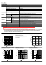
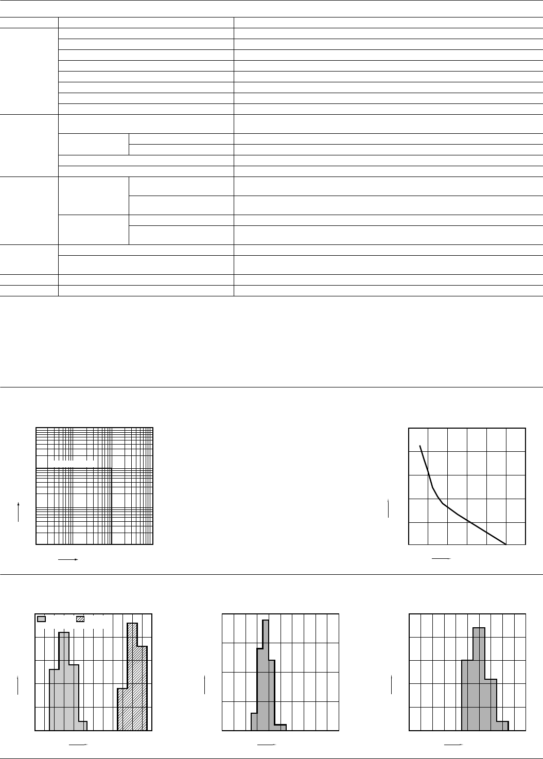
1. Maximum value for switching capacity 2. Carrying current limit
Connection electric wire: 40mm
2
Ambient temperature: 85°C 185°F
Standard for judgment: Relay contacts off when
carrying finished.
Carrying current and carrying time
1,000
100
10
10 100 1,000
Contact voltage, V
Contact current, A
DC resistive load
0.1
1
10
10000
1000
100
0 200 400 600 800 1000 1200
Carrying current, A
Carrying time, s
3. Distribution of pick-up and drop-out voltages
Tested sample: AEJ11012, 50 pcs.
4. Distribution of operate time
Tested sample: AEJ11012, 50 pcs.
5. Distribution of release time
Tested sample: AEJ11012, 50 pcs.
0
15
10
5
20
25
3.02.01.51.0 2.5 3.5 4.5 5.04.0 5.5 6.0 7.06.5
Pick-up
voltage
Drop-out
voltage
)(20°C 68°F
Voltage, V
Quantity
0
5
10
15
20
13.011.010.0 12.0 14.0 16.0 17.015.0 18.0 19.0 20.0
Time, ms
Quantity
)(20°C 68°F
0
5
10
15
25
20
1.50.50.0 1.0 2.0 3.0 3.52.5 4.0 4.5 5.0
Time, ms
Quantity
)(20°C 68°F
All Rights Reserved © COPYRIGHT Matsushita Electric Works, Ltd.