


Detector Switches/ESE22
Design and specifi cations are each subject to change without notice. Ask factory for the current technical specifi cations before purchase and/or use.
Should a safety concern arise regarding this product, please be sure to contact us immediately.
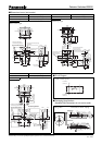
■ Circuit Diagram
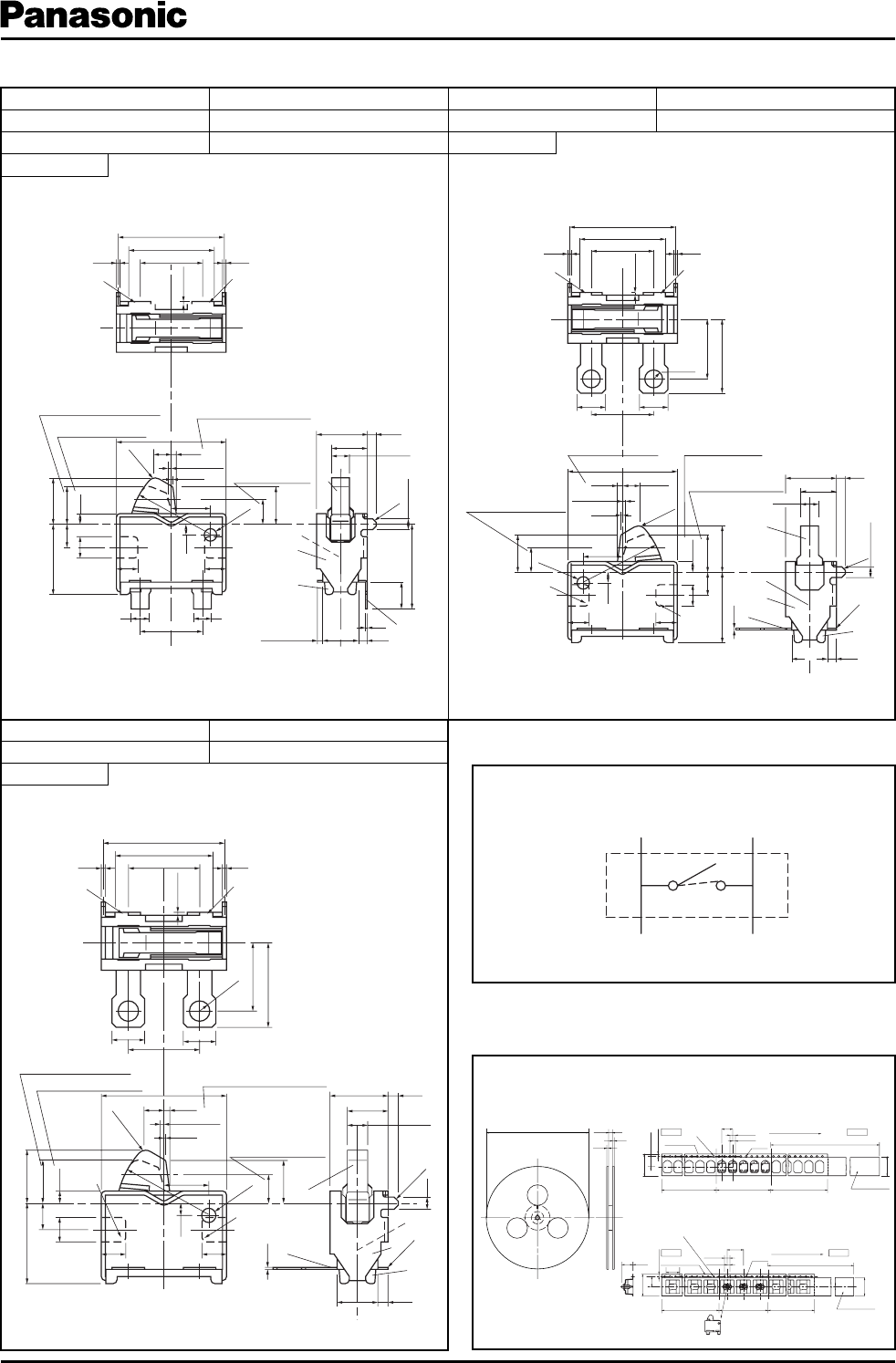
■ Packaging Specifi cations
Standard Reel Dimensions in mm (not to scale)
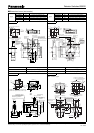
■ Dimensions in mm (not to scale)
Solder lug Type
With Frame Type
Solder lug Type
Part Numbers Packaging Part Numbers Packaging
ESE22MH53
Polyethylene Bag (Bulk)
ESE22MH57
Polyethylene Bag (Bulk)
ESE22MH54
Embossed Taping (Reel Pack)
Part Numbers Packaging
ESE22MH58
Polyethylene Bag (Bulk)
No. 7
1-pole 1-throw
No. 5
1-pole 1-throw
No. 6
1-pole 1-throw
Taping Reel Embossed Carrier Taping
1-pole 1-throw (N.O)
ESE22MH
ESE22MV
2.0
2.0
16.4
φ380.0±2.0
Carrier tape
Cover tape
Insert direction of switch
Carrier tape
TOPEND
Drawing direction
Pilot holes
Leading portion 400 mm min.
Cover tape
Packed portion
Non-packed portion
(100 mm min.)
Non-packed portion
(160 mm min.)
16.0±0.3
1.75±0.1
7.5±0.1
P=8.0±0.1
4.0±0.1
2.0±0.1
φ1.5
+0.1
0
13.5
16.0±0.3
1.75±0.1
7.5
P=12.0±0.1
4.0±0.1
2.0±0.1
φ1.5
+0.1
0
13.5
7.9 0.4
10.0
Drawing direction
Pilot holes
Leading portion 400 mm min.
Packed portion
(100 mm min.)
(160 mm min.)
Non-packed portion
Non-packed portion
TOPEND
Horizontal operation
ON starting position
Vertical direction
ON starting position
Horizontal ON position
measuring point
Full stroke position
Part A
Part A
Part A
0.1 min.
Part A
Part A
4.15
3.35
0.08
0.28
0.18±0.25
5.95
0.98
4.8
3.5 0.20.2
R0.4
5
6.15
3.5
1.6
1.6
2-
φ1
0.1
(2.1)
φ0
.
7
2.2
1.3
1.2 1.2
1.4
0.6
3.95
–0.2
+0.3
2.6
0.6
2.1
1.2
R4.55
0.5
1±0.1
2
C0.2
2
0.6
0.52.85
1
2
3
4
5
Common
terminal
Common
terminal
C
C
Part A
6.15
2.1
0.6
0.18±0.25
1.4
2.2
1.21.2
0.28
0.08
0.98
R4.55
R0.45
3.5
1.61.6
φ0.7
0.1
1.3
–0.2
+0.3
2.6
3.95
1.2
(2.1)
0.6
5
4
1
3
2
0.5
2.85 0.5
0.6
C0.2
2
1±0.1
2
5.95
0.2 0.2
3.5
4.8
0.1min.
2-φ1
4.15
3.35
Horizontal on position
measuring point
Horizontal on starting
position
Vertical direction
ON starting position
Full stroke position
Part A
Part A
Part A
Part A
Horizontal ON starting
position
Vertical direction
ON starting position
Horizontal ON position
measuring point
Full stroke position
Part A
Part A
0.1 min.
0.35 max.
5.95
4.8
3.5
0.20.2
(2.1)
0.08
0.28
φ0.
7
2.2
1.3
1.2 1.2
1.4
0.18±0.25
0.6
3.95
–0.2
+0.3
2.6
0.6
2.1
6.15
1.2
0.98
R
4.55
0.5
1±0.1
2
C0
.2
2
1.5
0.1
0.6
0.52.85
1
2
3
4
5
4.75
11
3.5
R0.45
Nov. 2005