


Chip RC Networks
Design and specifi cations are each subject to change without notice. Ask factory for the current technical specifi cations before purchase and/or use.
Should a safety concern arise regarding this product, please be sure to contact us immediately.
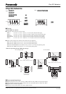
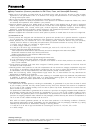
Preheating
Peak
Heating
Temperature
Time
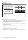
■ Recommended Soldering Conditions
Recommendations and precautions are described below.
The following are precautions for individual products. Please also refer to the precautions common to EMI Filters,
Fuses, and Sensors(MR Elements) shown on page EX2 of this catalog.
1. Take measures against mechanical stress during and after mounting of Chip RC Networks (hereafter called the RC networks)
so as not to damage their electrodes and protective coatings.
Be careful not to misplace the RC networks on the land patterns. Otherwise, solder bridging may occur.
2. Do not use halogen-based or other high-activity fl ux. Otherwise, the residue may impair the RC networks' performance
and/or reliability.
3. Perform suffi cient preheating so that the difference of the solder temperature and the RC networks chip surface
temperature becomes 100
°
C or less. Maintain the temperature difference within 100
°
C during rapid cooling by
immersion into solvent after soldering.
4. When soldering with a soldering iron, never touch the RC networks' bodies with the tip of the soldering iron. When
using a soldering iron with a high temperature tip, fi nish soldering as quickly as possible (within three seconds at
350
°
C max.).
5. As the amount of applied solder becomes larger, the mechanical stress applied to the RC networks increases, causing
problems such as cracks and faulty characteristics. Avoid applying an excessive amounts of solder.
6. Do not apply shock to the RC networks or pinch them with a hard tool (e.g. pliers and tweezers). Otherwise, the RC networks'
protective coatings and bodies may be chipped, affecting their performance.
7. Avoid excessive bending of printed circuit boards in order to protect the RC networks from abnormal stress.
8. The static capacitance may decrease by a few percent from the time of shipment due to the characteristics peculiar to
dielectric materials having a high dielectric constant.
Safety Precautions
●
Flow Soldering
We do not recommend fl ow soldering to the prod uct, because solder bridging may occur due to the
narrow pitch of the terminals and the characteristics of the product may be badly affected when using
adhesive to affi x it to a circuit board.
●
Recommended soldering conditions for refl ow
·R
efl ow soldering shall be performed a maximum of
two times.
·Please contact us for additional information when
used in conditions other than those specifi ed.
·Please measure the temperature of the terminals and
study every kind of solder and printed circuit board
for solderability be fore actual use.
For soldering (Example : Sn/Pb)
Temperature Time
Preheating 140 °C to 160 °C 60 s to120 s
Main heating Above 200 °C 30 s to 40 s
Peak 235 ± 5 °C max. 10 s
Temperature Time
Preheating 150 °C to 180 °C 60 s to 120 s
Main heating Above 230 °C 30 s to 40 s
Peak max. 260 °C max. 10 s
This product has circuits on both sides. Therefore, do not use
adhesives because they may impair the products characteristics.
For lead-free soldering (Example : Sn/Ag/Cu)
Feb. 2006