


ABP8
141
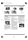
DIMENSIONS
Type I
Type II Recommended PC board pattern
(Top view)
Schematic
SPST-NO
C
L
3.4
.134
3.4
.134
2.3
.091
FP
3.7 max.
.146
OP
3.3
±0.2
.130
±.008
TTP
2.3 max.
.091
1.2
.047
0.15 max.
.006
0.25
.010
C0.1
.004
1.5
.059
1.0
.039
0.3
.012
1.0
.039
0.2
.008
1.2
±0.05
dia.
.047
±.002
dia.
0.8 dia.
.031 dia.
Terminal #3
Terminal #1
Terminal #2
C
L
2.3
.091
2.9
.114
FP
4.9 max.
.193
OP
4.5
±0.2
.177
±.008
TTP
3.5 max.
.138
0.15 max.
.006
0.25
.010
C0.1
.004
0.2
.008
1.2
±0.05
dia.
.047
±.002
dia.
0.8 dia.
.031 dia.
Terminal #3
Terminal #1
Terminal #2
3.7
.146
1.3 dia. hole
+0.2
−0
.051 dia. hole
+.008
−0
1.5
.059
0.7
.028
1.1
.043
1.1
.043
Terminal #3
Terminal #1
Terminal #2
NOTES
1. Soldering operations
1) For manual soldering;
By using 18W Max. (iron tip temperature:
320
°
C 608
°
F Max.) soldering should be
completed within 3 seconds.
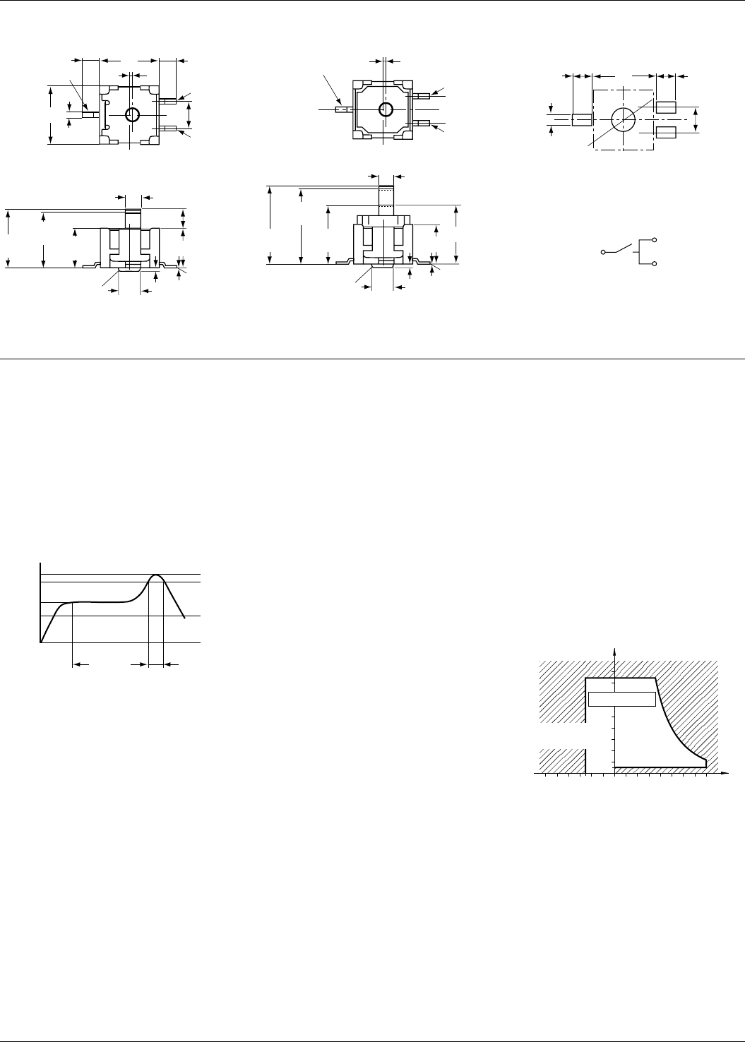
2) For reflow soldering;
Perform soldering reflow at a peak sur-
face temperature of the PC board not to
exceed 245
°
C 473
°
F. See the below rec-
ommended temperature profile.
3) During soldering, care should be taken
not to apply excessive stress to the termi-
nals as the resulting deformation may
cause malfunction. Excessively high sol-
der tab temperature and soldering iron
wattage should also be avoided as these
factors may harm switching performance.
2. Setting of the operation object
In setting the operation object; keep the
following distance between the switch bot-
tom and the operation object at T.T.P. (To-
tal Travel Position)
ABP811161P: 2.3 to 2.9mm
.091 to .114 inch
ABP811261P: 3.5 to 4.1mm
.138 to .161 inch
3. Quality Check under Actual Loading
Conditions
To assure reliability, check the switch un-
der actual loading conditions. Avoid any
situation that may adversely affect switch-
ing performance.
4. Environment
1) These switches do not have a sealed
construction. As such, the construction of
the equipment in which the switches are
to be installed should be given careful
consideration when the switches are to be
used in locations where corrosive gases,
silicon or other substances which will ad-
versely affect the contacts are used,
where there is a high concentration of
dust or where the switches may be ex-
posed to condensation or water. Using
switches in locations like these may cause
malfunctioning.
2) Avoid using this switch in high-temper-
ature, high-humidity or condensation-
forming environments and avoid allowing
droplets of water to remain on the switch
or come into contact with it. These condi-
tions may interfere with the performance
of the switch (resulting in short-circuiting,
migration, etc.). Use the type with the gold
contacts in applications involving trains,
aircraft, motor vehicles or medical equip-
ment where the switch must satisfy safety
and high reliability requirements. Please
consult with us for the applications re-
quired high reliability.
3) Because the humidity range differs de-
pending on the ambient temperature, the
humidity range indicated below should be
used. Continuous operation of the switch
is possible within this range, but continu-
ous use near the limit of the range should
be avoided.
• This humidity range does not guarantee
permanent performance.
Recommended condition for
reflow temperature profile
Temperature (°C °F)
Preheating
within 2 min.
with 30 sec.
245
473
220
428
150
302
Temperature, °C °F
Tolerance range
85
5
0
+32
80
176
–25
–13
(Avoid
condensation
when used at
temperatures
higher than 0°C 32°F)
Humidity, %R.H.
(Avoid freezing when
used at temperatures
lower than 0°C 32°F)
mm inch
01/2006