


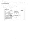
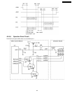
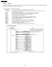

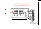
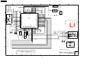

4.5.5.9. PCI I/F
The CPU ASIC (IC1) integrates a PCI Bus interface. The PCI I/F is the basic macro in CPU ASIC (IC1) for controlling the Mac&Phy
(IC6) that is a single-chip 10/100 Mb/s, via the PCI bus.
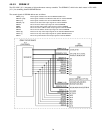
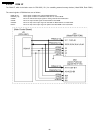
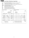
The control signals of the PCI I/F are as follows.
PCIAD [31:0]: These signals constitute the external Multiplexed address and data PCI bus.
nPCICBE [3:0]: During the address phase these signals define the “bus command”. During the data phase these pins indicate
which byte lanes contain valid data.
PCIREQ: This signal indicates that the IC6 requests the ownership of the bus to the CPU ASIC (IC1).
PCIGNT: This signal indicates that the CPU ASIC (IC 1) grants ownership of the bus to the IC6.
PCIFRM: This signal indicates the beginning and duration of a bus transaction.
PCIDSEL: This signal is the PCI Bus ID select signal.
PCIRDY: This signal indicates to be ready to complete the current data phase transaction.
PCITRDY: This signal indicates to be ready to complete the current data phase transaction.
nPCISTP: This signal indicates to request to stop the current transaction.
nPCIPERR: This signal indicates a parity error.
PCIPAR: This signal indicates even parity across PCIAD[31-0] and nPCICBE[3-0].
nPCISERR: This signal is asserted low during address parity errors and system errors.
nPCIINT: This signal is asserted low when an interrupt condition occurs.
PCIRST: This signal is the PCI Bus Reset signal.
PCICKOUT: This signal is the PCI Bus clock which provides timing for all bus phases.
86
KX-P7105 / KX-P7110