


Chapter 3 Register Setup of Each Function
64
001: Timer 3, prescaler output signal
010: Low speed crystal clock oscillation frequency
011: Synchronous low speed crystal clock oscillation frequency
110: Timer 3, pin input external signal
111: Synchronous timer 3, pin input external signal
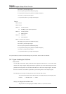
Timer 4:
BIT7: Unused
BIT6: Unused
BIT5: "0" Normal operation
"0" P24(IRQ4), pulse width measurement
BIT4: "0" Normal operation
"1" PWM operation
BIT3: "0" Stop count
"1" Count operation
BIT2, 1, 0: Clock source selection
000: High speed crystal clock oscillation frequency
001: Timer 4, prescaler output signal
010: Low speed crystal clock oscillation frequency
011: Synchronous low speed crystal clock oscillation frequency
110: Timer 4, pin input external signal
111: Synchronous timer 4, pin input external signal
The synchronization synchronizes with the timing of the system clock. See the "LSI User’s Manual".
3.9.1 Types of setting for 8-bit timer
Interval timer
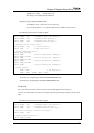
You can apply interval timer setting to all 8-bit timers ranging from the timer 0 to 4. Your source clock
selection and compare register setting determines the generation cycle of the timer interrupt. The timer
generates the interrupt on the next count after it matches the set value on the compare register, then clears
the count. You write a count which is equivalent to a period setting minus 1 to the compare register.
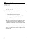
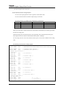
The following is the example for setting the interval timer with 10 milli seconds.
To set to the interval timer with 10 milli seconds, convert the time base to the frequency first.
Formula: 1 / 10 milli seconds = 100 Hz
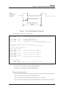
Setting by using
high speed oscillation clock:
The prescaler can set the high speed oscillation clock to 4, 16, 32 or 64 divisions.