


INSTALLATION INSTRUCTIONS PN347
E-mail:
cs@panduit.com
Fax:
(708) 444-6993
For Instructions in Local Languages
and Technical Support:
www.panduit.com/resources/install_maintain.asp
www.panduit.com
Page 3 of 3
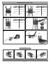
TERMINATION CAP REMOVAL
Notes:
1. For specified performance, follow TIA/EIA 568-B installation guidelines.
2. Jack Modules can terminate PVC or Plenum rated 22-24 AWG solid or
stranded IWC cable with 0.048 inch (1.2 mm) maximum insulated
conductor outside diameter.
3. Jack Modules may be re-terminated a minimum of 10 times.
4. For technical and performance information, consult PANDUIT Technical
Support.
As with all Wiring Accessories, the following statements apply:
1. Never install communications wiring during a lightning storm.
2. Never install communications wiring in wet locations unless the jack is
specifically designed for use in wet locations.
3. Never touch uninsulated communications wiring or terminals unless the
communication line has been disconnected at the network interface.
4. Use caution when installing or modifying communication wiring.
8
7
6
5
4
3
2
1
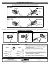
7 8
4 6
5 3
2 1
Brown
White/Brown
Orange
White/Blue
Blue
White/Orange
Green
White/Green
BOTTOM
TOP
8
7
6
5
4
3
2
1
Brown
White/Brown
Green
White/Blue
Blue
White/Green
Orange
White/Orange
BOTTOM
TOP
7 8
4 6
5 3
2 1
T568-A
G
IGA-TX Wiring Sequences
T568-B
18
Pin #’s
1 2
3
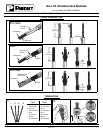
TELECOMMUNICATION ROOM SHIELDING CONTINUITY
2
3
1
Drain wire
FTP / ScTP
All Metal Patch
Panel Shielding
(OR)
CJSGK-X Kit
2
3
1
S-FTP, STP / PIMF,
S-STP / PIMF
All Metal Patch
Panel Shielding
(OR)
CJSGK-X Kit