


Page 2 of 2
INSTALLATION INSTRUCTIONS PN366E
For Instructions in Local Languages
and Technical Support:
http://www.panduit.com/resources/install_maintain.asp
E-mail:
info@panduit.com
Fax:
(708) 444-6993
www.panduit.com
Cable End 1
Cable End 2
Cable End 1
Cable End 2
7
T568B
T568A
A
B
A
B
A
B
1
2
1
3
1
2
3
1
2
3
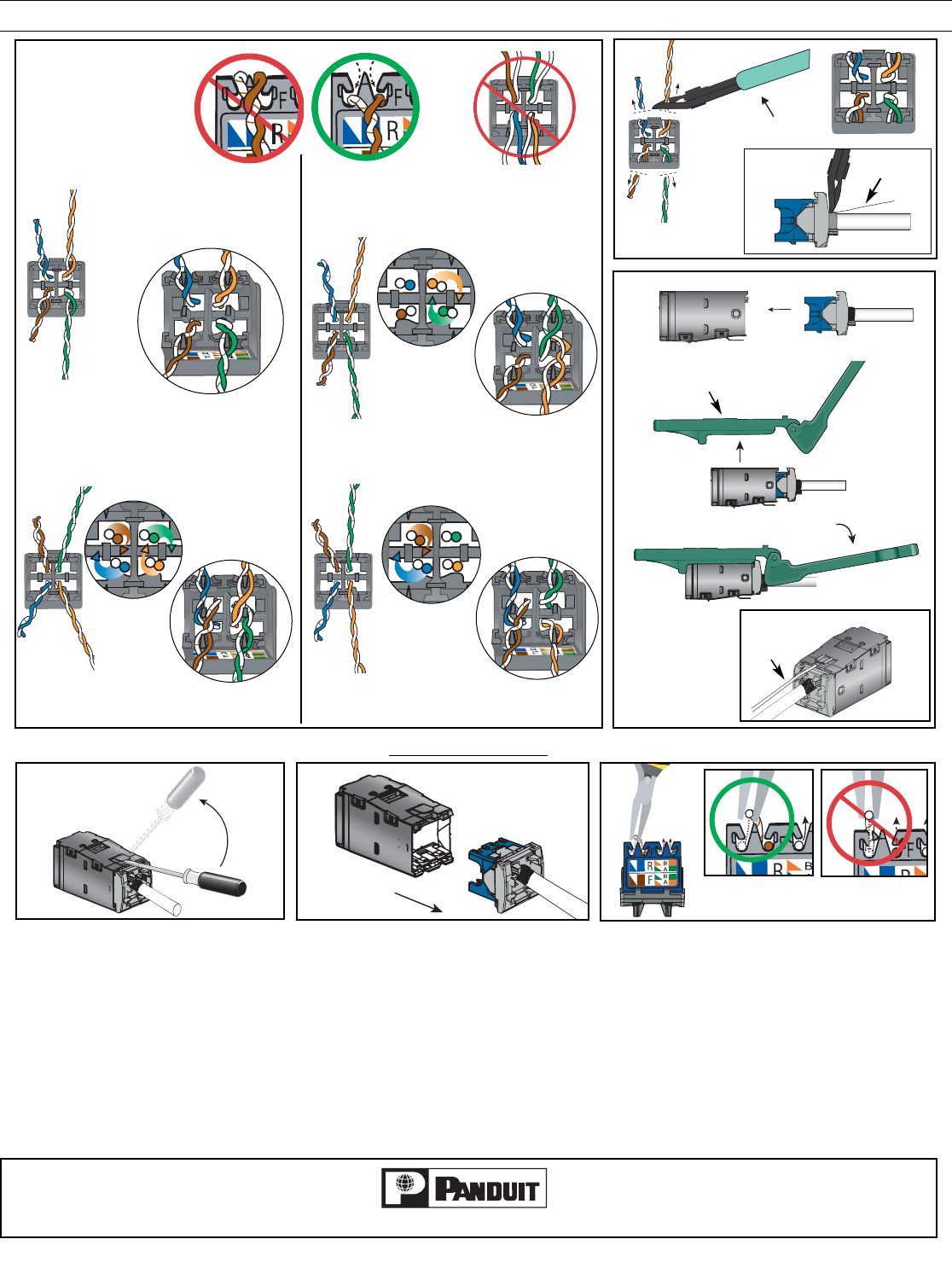
See note 4.
2
CWST
8
9
EGJT
10
11
CJSGK-X
KIT
1
2
REMO
VAL STEPS
3
Notes:
1. For specified performance, follow TIA/EIA 568-B installation guidelines.
2. Jack Modules can terminate PVC or LSZH rated 22-26 AWG solid or stranded IWC cable with 0.048 inch (1.2 mm)
maximum insulated conductor outside diameter.
3. Jack Modules may be re-terminated a minimum of 20 times.
4. On cable end 2 for A & B wiring and cable end 1 of A wiring, wrap the designated pairs around the proper center dividing post (A or B) and terminate in the proper
location.
5. CJSGK-X Grounding Kit is REQUIRED for all M
INI-COM Modular Patch Panels, but is optional for MINI-COM All Metal Shielded Modular Patch Panels.
6. For technical and performance information, consult PANDUIT Technical Support.
As with all Wiring Accessories, the following statements apply:
1. Never install communications wiring during a lightning storm.
2. Never install communications wiring in wet locations unless the jack is specifically designed for use in wet locations.
3. Never touch uninsulated communications wiring or terminals unless the communication line has been disconnected at the network interface.
4. Use caution when installing or modifying communication wiring.
See note 5
12
Drain Wire
U/FTP