13
3980-A2-GZ40-20
November 1996
Data Synchronization
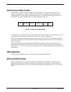
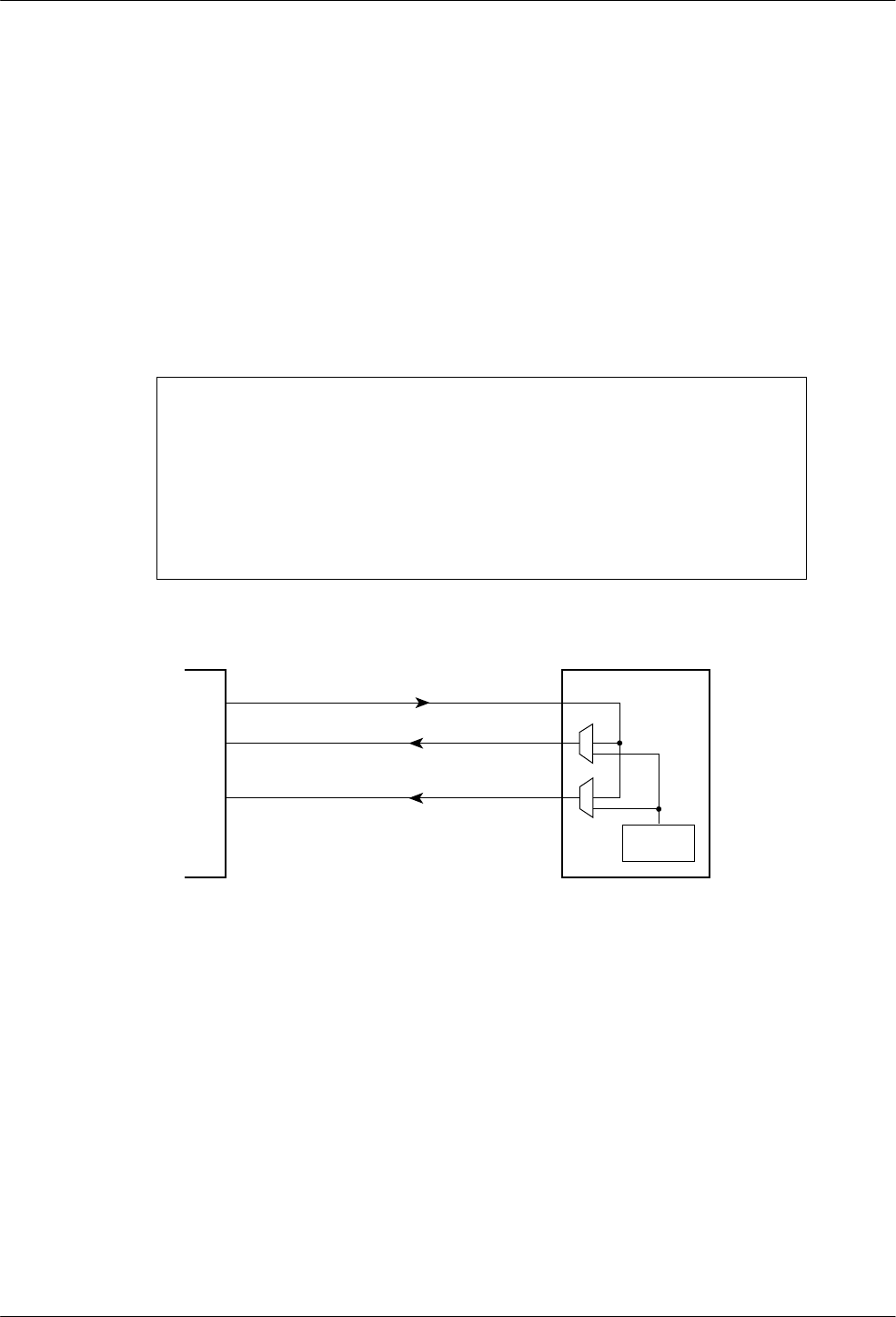
Data exchanged between the synchronous DTE and the modem is synchronized by two clock signals. Data
coming from the DTE is synchronized by the transmit clock and data received by the DTE is synchronized by the
receive clock. The transmit clock is provided by the modem on circuit 114 or by the synchronous DTE on
circuit 113. The receive clock is provided by the modem on circuit 115.
When the transmit clock is provided by the modem, the transmit and receive clocks are locked on the same clock
source internal to the modem. In this configuration, the user can select rates on the DTE-DCE line (or clock
frequencies) in the range from 1.2 kHz to 128 kHz.
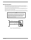
When the transmit clock is provided by the DTE, the receive clock is set by the modem equal to the DTE clock
(Figure 4). When SDC is in use, the Tx Clock Source configuration option cannot be set to Receiver Clock Loop.
NOTE
When faster speeds are used (above 57.6 kHz), and the transmit clock is
provided by the modem, data transmission can be sensitive to DTE cable
length and capacitance, as well as the DTE’s drivers and receivers. Should
you encounter bit errors related to the above conditions, you may want to
change the Tx Clock Source configuration option setting to External
(provided the DTE can support the required transmit clock signal) or
change the length of the DTE cable.
CLOCK
SOURCE
DCE
DTE
XTCLK (113)
TXC (114)
RXC (115)
495-1478
2
Figure 4. Clocks at the DTE–DCE Interface


