BSX8-A2-GZ40-10 March 2005 13
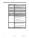
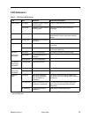
LED Indicators
Table 2. LED States and Meanings
LED State Indication Additional Information
PWR (Power) Solid green BSX8000-5 uplink module is
receiving power
Both BLC power terminals are connected.
Solid amber BSX8000-5 uplink module is
receiving power
Only one of the BLC power terminals is
connected.
No illumination No power The BSX8000-5 uplink module is not receiving
power (the BLC may or may not be receiving
power).
OK Pulsing green* BSX8000-5 uplink module is
operational
Fan Solid green All fans are functioning All four of the fans on the BLC fan card are
functioning.
Solid amber Non-functioning fan At least one of the four fans on the BLC fan card
is no longer functioning.
Lnk (Link)
Uplink Ports
and MGMT
Solid green GigE link established The MGMT port does not support GigE.
Solid amber Link established at 10 or
100 Mbps
No illumination No link is established
Act (Activity)
Uplink Ports
and MGMT
Flashing green* Traffic flowing on link
Dup (Duplex)
Uplink Ports
and MGMT
Solid green Full duplex mode
No illumination Half duplex mode
[MIM] Lnk
(Link)
Solid green MIM-10/100, MIM100F,
MIM-2000F, MIM-4000F,
uplink connection is
established
For further information regarding MIM LEDs,
please refer to the corresponding MIM Installation
Instructions.
Flashing green*
*
A pulsing LED blinks steadily at a rate of once per second. A flashing LED blinks at a more rapid,
less constant rate.
MIM-2T1 or MIM-2E1 uplink
connection is established
For further information regarding MIM LEDs,
refer to the corresponding MIM Installation
Instructions.
No illumination No uplink connection is
established
Applicable to all MIM model types.


