


Verify the connection: the Lnk (link) LED on the UIM-DS3 and UIM-E3 faceplate will flash green
to indicate a network connection has been established.
For further information refer to the Installation Instructions for each individual UIM model.
2.0 IP DSLAM MANAGEMENT
The MUM200-2 provides IP DSLAM management capability via Net to Net's web-based Network
Management System (NMS) and a scaled-down version of Simple Network Management Protocol (SNMP).
For access and configuration instructions, refer to Net to Net's NMS Management User Guide.
3.0 ADDITIONAL INFORMATION
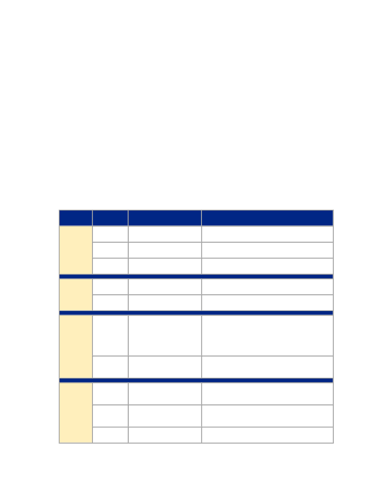
3.1 LED Indications
LED
State Indication Additional Information
PWR
(Power)
solid green MUM200-2 is receiving
power
Both IP DSLAM power terminals are connected.
solid amber MUM200-2 is receiving
power
One of the two IP DSLAM power terminals are
connected.
no
illumination
no power The MUM200-2 is not receiving power (the IP
DSLAM may not be receiving power either).
Fan no
illumination
all fans are functioning All four of the fans on the IP DSLAM fan card are
functioning.
solid amber non-functioning fan One or more of the four fans on the IP DSLAM fan
card are no longer functioning.
Lnk (Link) solid green direct Ethernet
management connection is
established
The Lnk LED applies only to direct physical
connections with the MGMT port; it does not
apply to uplink network connections.
The MGMT Ethernet port runs at 10 Mbps and
Half Duplex.
no
illumination
no direct connection via
the MGMT port is
established
UIM Lnk
(Link)
solid green UIM-10/100 Ethernet
uplink connection is
established
For further information regarding UIM-10/100
LEDs, please refer to the corresponding UIM
Installation Instructions.
flashing
green
UIM-T1/E1 or UIM-DS3/E3
uplink connection is
established
For further information regarding UIM-T1/E1 or
UIM-DS3/E3 LEDs, please refer to the
corresponding UIM Installation Instructions.
no
illumination
no uplink connection is
established
Applicable to all UIM models types.
220-0000069 rev 04