


220-0000016 rev01
c. Remove the blanking plate* from the selected port.
d. Carefully slide the faceplate of the UIM under the inside lip of the Mini DSLAM at the
selected port opening such that the UIM circuit board is facedown and the UIM label
shows through the port opening with the model name along the right-hand edge.
e. Ensure the mounting holes on the UIM are lined up with the corresponding pems on the
Mini DSLAM board and the board-to-board connector key pins are properly aligned.
f. Gently press down with even pressure on all four corners of the UIM until the board-to-
board connector is fully seated.
g. Secure the boards together at the pems with the (4) provided panhead screws.
h. Secure the UIM faceplate to the front of the Mini DSLAM chassis using the (2) provided
beige flathead screws.
i. Replace the Mini DSLAM chassis cover and secure with the original (8) screws.
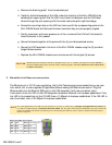
3. Establish the Ethernet connection.
The Ethernet port is 10/100 auto-negotiating. Net to Net Technologies recommends that you set your
hub, switch, etc. to auto-negotiate (if applicable) before making the Ethernet connection. Plug the
Ethernet cable into the Ethernet RJ45 port on the UIM faceplate. Verify the connection; solid
illumination of the Lnk LED on the UIM faceplate indicates an Ethernet link has been established. If the
Lnk LED is illuminated but not the 100 LED then a 10 Mbps link has been established. If the 100 LED is
also illuminated, then a 100 Mbps link has been established.
CAUTION
*Blanking plates should be stored for possible future use. If a UIM is removed from a Mini DSLAM, it
must be replaced with either another UIM or a blanking plate. DO NOT OPERATE A MINI DSLAM WITH
AN EMPTY UIM PORT.
NOTE
For most applications, the UIM-10/100 connects to a router or a PC using a straight-through Ethernet cable and
to a hub or a switch using a crossover Ethernet cable. For any other connection combinations you must verify the
pinout of the Ethernet device into which you are connecting the UIM-10/100 in order to determine which type of
cable is required.
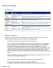
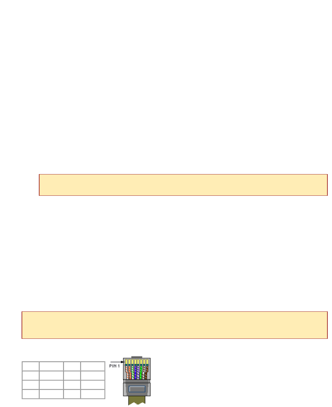
Ethernet RJ45 Port Pinout
Pin 1 RX+ Pin 5 not used
Pin 2 RX- Pin 6 TX-
Pin 3 TX+ Pin 7 not used
Pin 4 not used Pin 8 not used