


SmartNode 5300 Quick Start Guide 3
1.0 Power Up SmartNode
• 1. Insert the barrel type connector end of the AC power cord into the external power supply connector.
• 2. Insert the female end of the power cord into the internal power supply connector.
• 3. Verify that the AC power cord included with your router is compatible with local standards. If it is not, con-
tact Patton to replace it with a compatible power cord.
• 4. Connect the male end of the power cord to an appropriate power outlet.
• 5. Wait until the Power LED stops blinking and remains constantly lit. Now the SmartNode is ready to config-
ure.
2.0 Configuring the SmartNode
Refer to the following manuals (available online at http://www.patton.com/kb/index.asp?dt=Manu-
als%20(PDF)
) for detailed information about installing, configuring, operating, and troubleshooting
the SmartNode:
• SmartNode 5300 User Manual: http://www.patton.com/manuals/SN5300-qs
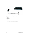
3.0 Connection via Console Access
The SmartNode can be connected to a serial terminal over its serial console port, as depicted in figure 1.
• Always follow ESD prevention procedures when removing and replac-
ing cards.
• Wear an ESD-preventive wrist strap, ensuring that it makes good skin
contact. Connect the clip to an unpainted surface of the chassis frame
to safely channel unwanted ESD voltages to ground.
• To properly guard against ESD damage and shocks, the wrist strap and
cord must operate effectively. If no wrist strap is available, ground
yourself by touching the metal part of the chassis.
The interconnecting cables shall be acceptable for external use and shall be rated for the
proper application with respect to voltage, current, anticipated temperature, flammability,
and mechanical serviceability.
WARNING
CAUTION