


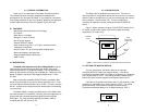
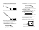
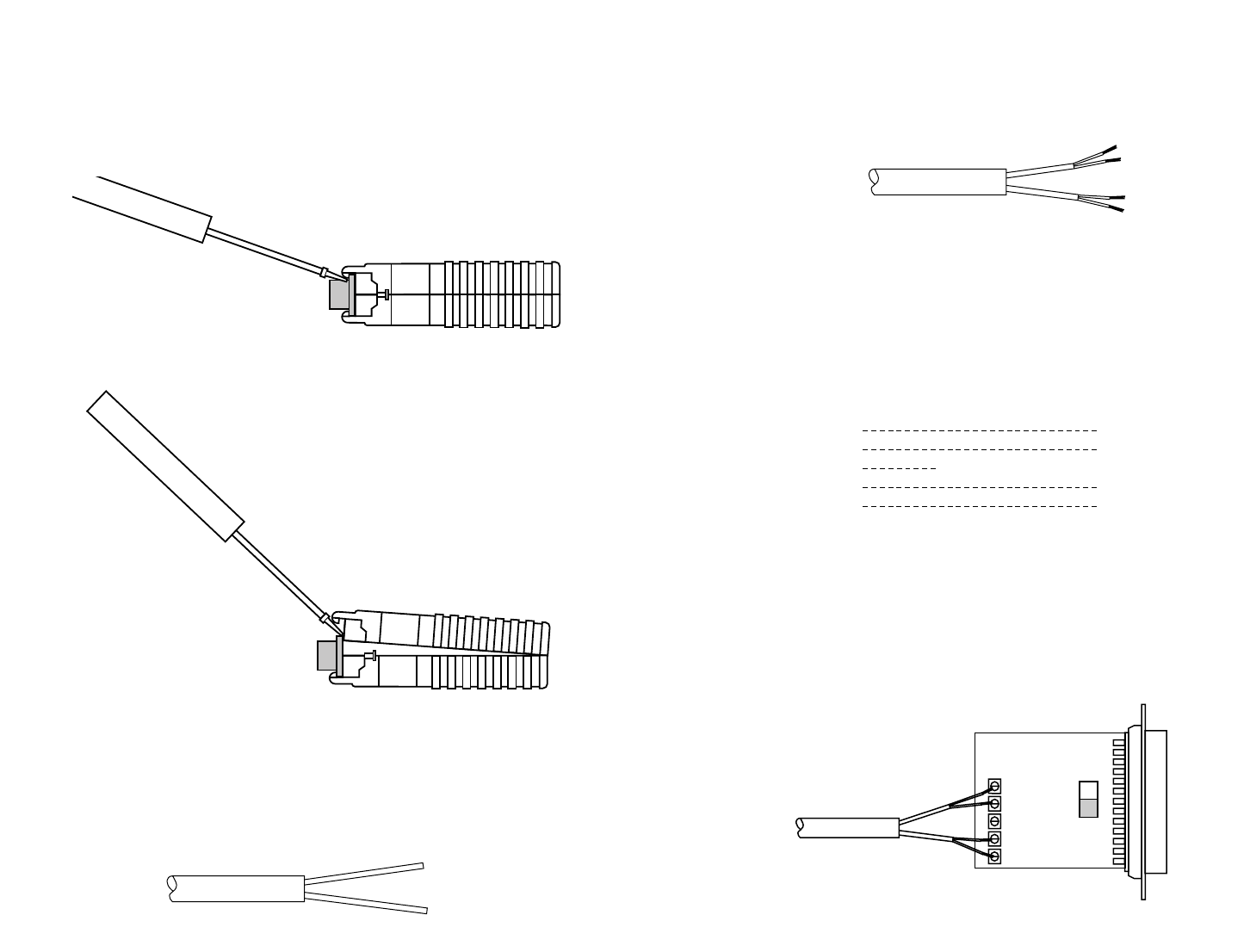
1. Open the unit by gently inserting a screwdriver between the
DB-25 connector and the lip of the plastic case (see Figures 4 and 5,
below). You don't have to worry about breaking the plastic, but be
careful not to bend the D-sub connector.
Once the unit has been opened, you will be able to see the
terminal blocks located at the rear of the PC board.
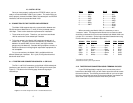
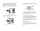
2. Strip the outer insulation from the twisted pairs about one inch
from the end as shown in Figure 6.
7
3. Strip the insulation on each of the twisted pair wires about .25"
as shown in Figure 7.
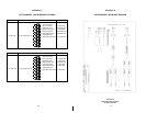
4. Connect
one pair
of wires to XMT+ and XMT- (transmit positive
and negative) on the terminal block, making careful note of which color
is positive, and which color is negative.
5. Connect the
other pair
of wires to RCV+ and RCV- (receive
positive and negative) on the terminal block, again making careful note
of which color is positive and which color is negative.
6. If there is a shield around the telephone cable, it may be
connected to "G" on the terminal block. To avoid ground loops, we
recommend connecting the shield at one end only. A ground wire is
not
necessary
for proper operation of the Model 1000.
7. When you finish connecting the wires to the terminal block, the
assembly should resemble the diagram in Figure 8, below:
8
+RCV- G -XMT+
XMT + RCV+
XMT - RCV -
GG
RCV - XMT -
RCV + XMT+
To Shield (Optional)
}
One Pair
}
One Pair
Figure 4: How to Use a Small Flathead Screwdriver to Begin to Open the Model 2070 Case
Figure 5: How to Use a Small Flathead Screwdriver to Finish Opening the Model 2070 Case
Figure 6: Stripping the Outer Insulation from the Twisted Pair
Figure 7: Stripping the Insulation from Each Twisted Pair
Figure 8: Proper Twisted Pair Connections to the Model 1009 Terminal Blocks