


5 6
3.0 CONFIGURATION
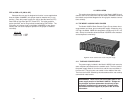
This section describes the location and orientation of the Model
1004ABRC's configuration switches, provides detailed instructions on
setting each switch and describes the settings for each of the rear con-
nection cards.
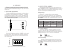
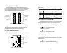
3.1 FRONT CARD CONFIGURATION
The Model 1004ABRC front card houses two short hauls–Modem
A and Modem B–
each
using two sets of DIP switches. The locations
of these switches are shown in Figure 1 (below). These switches are
accessible when the card is slid out of the rack chassis. Once config-
ured, the Model 1004ABRC is designed to operate transparently, with-
out need for frequent re-configuration.
Each of the DIP switches on the Model 1004ABRC function card is
a 4-position switch. Figure 2 (below) shows the On/Off orientation of
these switches. Use a small screw driver or similar instrument to set
each individual switch.
3.1.1 SWITCH SETTINGS - MODEM “A”
DIP switches S1 and S2 configure short range Modem A on the
Model 1004ABRC front card. The tables below provide an overview of
Modem A switch settings, including factory default settings. Following
the tables is a descriptions of each switch’s function.
SWITCH SET “S1”
DIP switch S1 is used to configure receive impedance,
RTS/CTS delay, carrier control operation and “echo” enable/disable.
The summary table below shows the factory default settings for switch
S1. Following the summary table is a detailed description of each indi-
vidual switch.
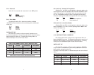
S1-1: Receive Impedance
The setting for switch S1-1 selects the impedance of the input
receiver. You may select either a “low” impedance of 120 Ohms or a
“high” impedance of 16K Ohms. By selecting the proper impedance for
each drop, there may be up to 50 receivers in one application.
S1-1
Setting
On Low (120 Ohm)
Off High (16K Ohm typical)
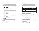
S1-2: RTS/CTS Delay
The setting for switch S1-2 determines the amount of delay
between the time the Model 1004ABRC “sees” RTS and when it turns
on CTS. Note: RTS/CTS Delay setting should be based upon trans-
mission timing.
S1-2
Setting
On 8 msec
Off no delay
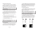
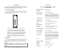
Figure 1. Model 1004ABRC Card, showing location of configuration switches.
ON
OFF
Figure 2. Close-up of DIP switches, showing ON/OFF orientation.
1234
ON
S2
S1
S3
S4
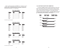
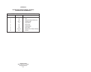
SWITCH S1 SUMMARY TABLE (factory defaults in bold)
Position Function ON Position OFF Position
S1-1 RX Impedance 120 Ohm 16K Ohm
S1-2 RTS/CTS Delay 8 msec No Delay
S1-3 Reserved - Default Setting
S1-4 Echo Mode Echo ON Echo OFF