


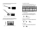
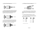
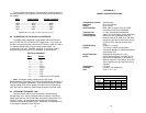

Figure 6 (below) shows how to wire the two-pair cables properly for
a Model 1008 daisy chain topology. Note that the ground connection is
not needed.
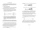
4.3 CONNECTION TO THE EIA/TIA-574 INTERFACE
The Model 1008 is designed to plug directly into the DB-9 serial
port of an EIA/TIA-574 DTE device (PC, laptop, host). If you must use
a cable to connect the Model 1008 to the DTE device, make sure that it
is a
straight through
cable of the shortest possible length—we
recommend 6 ft or less. The DB-9 connector on the Model 1008 is
wired according to the EIA/TIA-574 Standard, as shown below:
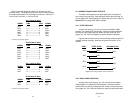
EIA/TIA-574 Standard
DB-9
SIGNAL
1 -----------------CD
2 -----------------RD
3 -----------------TD
4 -----------------DTR
5 -----------------SG/FG
6 -----------------DSR
7 -----------------RTS
8 -----------------CTS
9 -----------------(Optional 6-12 VDC power)
Note: The Model 1008 is configured as a DCE (Data
Communications Equipment), and is therefore designed to connect to a
DTE (Data Termination Equipment). If you need to connect the Model
1008 to another DCE device, please call Patton Technical Support at
(301) 975-1007 for details on constructing the proper crossover cable.
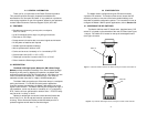
4.4 OPERATING THE MODEL 1008
Once the Model 1008 is properly installed, it should operate
transparently—as if it were a standard cable connection. Operating
power is derived from the RS-232 data and control signals; there is no
“ON/OFF” switch. All data signals from the RS-232 and RS-485
interfaces are passed straight through. Additionally, one hardware flow
control signal is passed
in each direction
.
APPENDIX A
MODEL 1008 SPECIFICATIONS
Transmission Format: Asynchronous
Data Rate: Up to 115,200 bps
Range: Up to 9 miles
Serial Interface: DB-9, male or female; wired as a DCE
according to EIA/TIA-574 Standard.
Transmit Line: 2, 4 wire unconditioned twisted pair
Transmit Mode: 4-wire, full or half duplex; 2-wire half duplex
Control Signals: DSR turns “ON” immediately after the
terminal raises DTR; DCD turns “ON” after
recognizing the receive signal from the line;
CTS turns “ON” after the terminal raises
RTS.
RTS/CTS Delay: 8 mSec or “no delay”
Carrier: The carrier is switch selected either
continuous operation or switched operation,
controlled by RTS
Surge Protection: 600W power dissipation at 1 mS
Power: Draws operating power from EIA/TIA-574
data and control signals; no AC power or
batteries required. If necessary, 6-12 VDC
can be applied to pin 9 of the EIA/TIA-574
interface.
Temperature: 0 to 50º C
Humidity: 5 to 95%, non-condensing
Size: ”2.50" x 1.2" x .75"
15 16
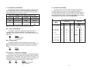
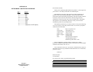
Data Rate
(kbps)
115.2 3.5 2.6 1.4 0.9
38.4 5.0 2.9 2.2 1.5
9.6 7.1 4.6 3.5 2.8
1.2 9.0 6.5 5.0 3.9
Model 1008 Distance Table (miles)
Wire Gauge
19 22 24 26
HOST FIRST SLAVE OTHER SLAVE(S)
XMT+---------------------RCV+-----------------------RCV+
XMT- ---------------------RCV- -----------------------RCV-
RCV+---------------------XMT+-----------------------XMT+
RCV- ---------------------XMT- -----------------------XMT-
Figure 6. Daisy chain wiring for Model 1008 host and slaves