


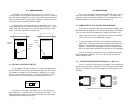
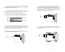
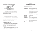
1. Open the unit by gently inserting a screwdriver between the
DB-15 connector and the lip of the plastic case (see below). You don’t
have to worry about breaking the plastic, but be careful not to bend the
D-sub connector.
Once the unit has been opened, you will be able to see the termi-
nal blocks located at the rear of the PC board.
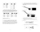
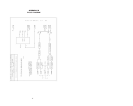
2. Strip the outer insulation from the twisted pairs about one inch
from the end.
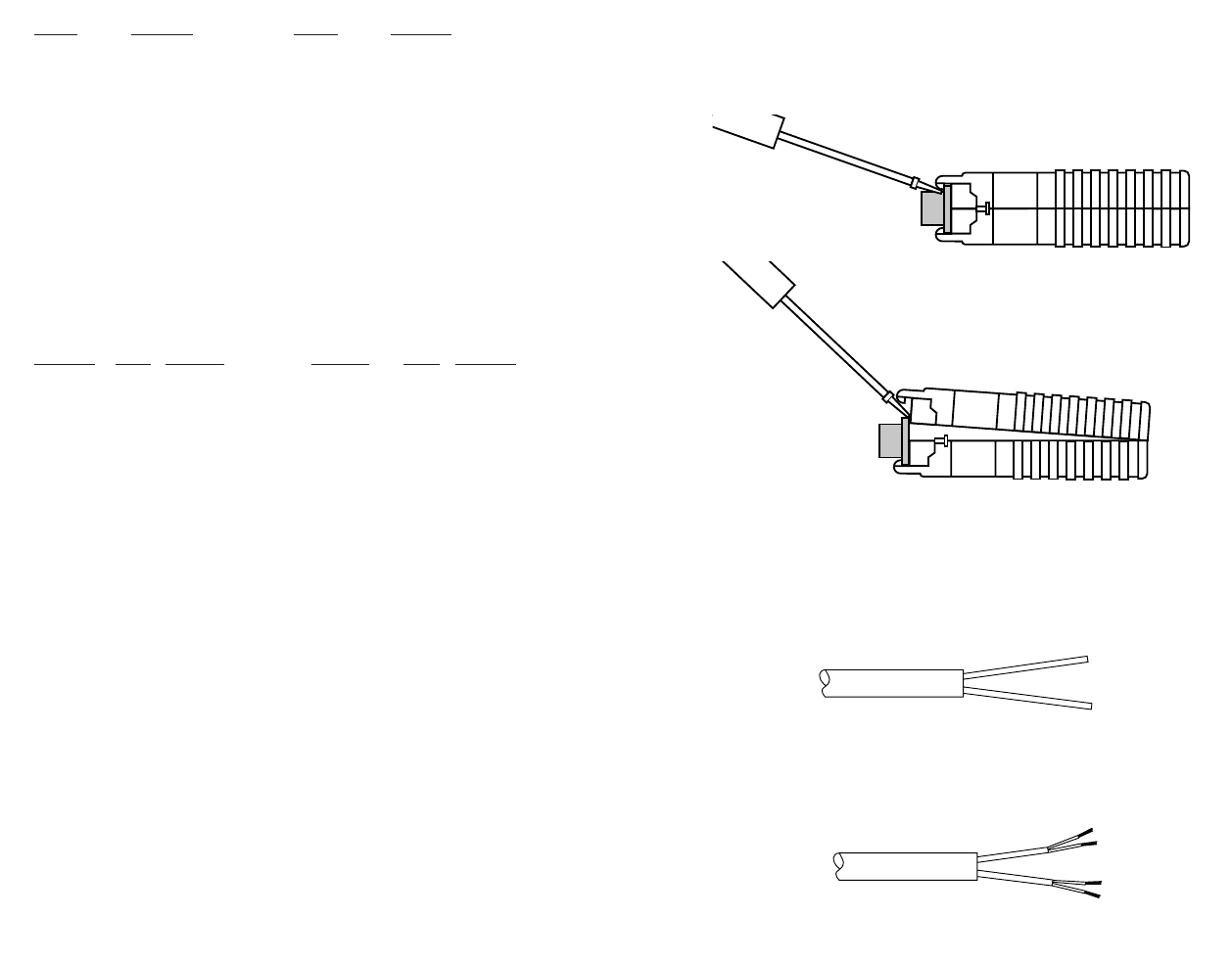
3. Strip the insulation on each of the twisted pair wires about .25”.
RJ-11 SIGNAL RJ-45 SIGNAL
1----------------GND
†
1----------------N/C
2----------------RCV- 2----------------GND
†
3----------------XMT+ 3----------------RCV-
4----------------XMT- 4----------------XMT+
5----------------RCV+ 5----------------XMT-
6----------------GND
†
6----------------RCV+
7----------------GND
†
8----------------N/C
When connecting two Model 1015s, it is necessary to use a
“cross-over” cable. The diagram below shows how a crossover cable
should be constructed for an environment where both Model 1015s use
a 4-wire RJ-11 connector. Similar logic should be followed when
using RJ-45 connectors or a combination of the two.
SIGNAL
PIN# COLOR
‡
COLOR PIN# SIGNAL
GND
†
1 Blue --------------------White 6 GND
†
RCV- 2 Yellow------------------Red 4 XMT-
XMT+ 3 Green ------------------Black 5 RCV+
XMT- 4 Red---------------------Yellow 2 RCV-
RCV+ 5 Black -------------------Green 3 XMT+
GND
†
6 White-------------------Blue 1 GND
†
†
Connection to ground is optional
‡
Standard color codes—yours may be different
4.1.2 TWISTED PAIR CONNECTION USING TERMINAL BLOCKS
If your RS-232 application requires you to connect two pairs of
bare wires to the Model 1015, you will need to open the case to access
the terminal blocks. The following instructions will tell you how to open
the case, connect the bare wires to the terminal blocks, and fasten the
strain relief collar in place so that the wires won’t pull loose.
5 6