


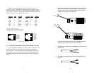

3.2 SWITCH SETTINGS
All possible settings for the Model 1020’s configuration switches
are presented in the summary table and descriptions below. If you
have additional questions regarding configuration, contact Patton
Technical Support at (301) 975-1007.
Switch 1: RTS/CTS Delay
After request to send (RTS) is raised by the host terminal, the
1020/1020S raises CTS after a slight delay in order to give the remote
terminal time to receive an incoming signal. Depending on the type of
environment, either a 7mS or 53mS delay can be selected.
Switch 1
Setting
On 7 mS
Off 53 mS
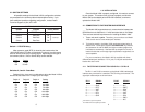
Switches 2, 3 and 4: Data Rate
Switches 2 thru 4 are set in combination to allow the Model 1020 to
be used at data rates from 1.2 Kbps up to 19.2 Kbps.
Switch 2 Switch 3 Switch 4 Setting
On On On 1.2 Kbps
On On Off 2.4 Kbps
On Off On 4.8 Kbps
Off On On 7.2 Kbps
On Off Off 9.6 Kbps
Off On Off 14.4 Kbps
Off Off On 19.2 Kbps
Off Off Off 19.2 Kbps
5
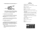
4.0 INSTALLATION
Once the Model 1020 is properly configured, it is ready to connect
to your system. This section tells you how to properly connect the
Model 1020 to the twisted pair and RS-232 interfaces, and how to
operate the Model 1020.
4.1 CONNECTION TO THE TWISTED PAIR INTERFACE
The Model 1020 supports data-only communication between two
RS-232 devices at distances to 11 miles and data rates to 19.2 Kbps.
There are two essential requirements for installing the Model 1020:
1. These units work in
pairs
. Therefore, you must have one Model
1020 at each end of a two twisted pair interface.
2. To function properly, the Model 1020 needs two twisted pairs of
metallic wire. These pairs must be
unconditioned
, dry, metallic
wire, between 19 and 26 AWG (the higher number gauges may
limit distance somewhat). Standard dial-up telephone circuits, or
leased circuits that run through signal equalization equipment, are
not acceptable
.
For your convenience, the Model 1020 is available with three
different twisted pair interfaces: RJ-11 jack, RJ-45 jack and terminal
blocks with strain relief.
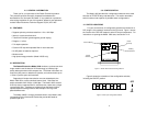
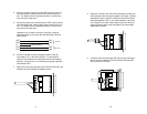
4.1.1 TWISTED PAIR CONNECTION USING RJ-11 OR RJ-45
The RJ-11 and RJ-45 connectors on the Model 1020’s twisted pair
interface are pre-wired for a standard TELCO wiring environment. The
signal/pin relationships are shown below:
RJ-1
1 SIGNAL RJ-45 SIGNAL
1...................GND
†
1 .................N/C
2...................RCV
‡
2 .................GND
†
3...................XMT 3 .................RCV
‡
4...................XMT 4 .................XMT
5...................RCV 5 .................XMT
6...................GND 6 .................RCV
7 .................GND
8 .................N/C
†
Connection to ground is optional
‡
The Model 1020 is not polarity sensitive
6
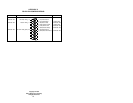
SWITCH SUMMARY TABLE
Position Function Factory Default
Switch 1 RTS/CTS delay On
7 mSec delay
Switch 2 Data Rate On
Switch 3 Data Rate Off
Switch 4 Data Rate Off
9,600 bps
}