


4.2.2 STAR TOPOLOGY
Using a star topology, you may connect several Model 1050s
together in a master/slave arrangement. Maximum distance between
the units will vary based upon the number of drops, data rate, wire
gauge, etc. Call Patton Technical Support for specific distance
estimates.
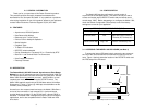
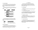
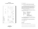
Figure 4 (below) shows how to wire the two-pair cables properly for
a Model 1050 star topology. Note that the ground connection is not
needed.
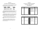
In a multipoint topology, you must configure the master Model
1050's carrier control strap differently than those of the slave Model
1050(s). Here are the proper carrier control strap settings for a star
topology:
Function
Carrier Control Strap Setting
Master Carrier “Constantly ON” (pegs 2 & 3)
Slave(s) Carrier “Controlled by RTS” (pegs 1 & 2)
4.3 RS-232 CONNECTION
To connect the Model 1050 to a piece of data terminal or data
communications hardware, use a
straight through
RS-232 cable. Plug
the cable directly into the DB-25 port on the rear of the Model 1050.
The DCE/DTE switches eliminate the need for a crossover cable.
5.0 OPERATION
Once you have configured each Model 1050 properly and
connected it, simply plug in the AC power adapter to get it running;
there is no power switch on the Model 1050. You can monitor the
operation of the Model 1050 using the front panel LED indicators and
built-in loopback test modes.
5.1 LED INDICATORS
The Model 1050 incorporates three front panel LEDs that show the
status of the modem:
1. The loopback test LED glows when the loopback test switch
has been depressed and is in a test mode.
2. The tri-state TD and RD indicators blink red and green with data
activity. Solid red indicates a low RS-232 logic level. Note: RS-232
devices idle in a low state, so the LED will glow red if the connections
are correct and the RS-232 device is in an idle state.
5.2 LOOPBACK TEST MODES
Select the test modes by depressing the "Loopback Test" switch.
When in loopback mode, the "Loopback Test" LED will glow red. Two
tests are possible using this switch: Local Analog Loop (LAL), and
Remote Analog Loop (RAL).
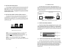
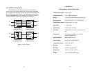
5.2.1 LOCAL ANALOG LOOP
The first test mode is Local Analog Loop (V.54 Loop 3). Any data
sent to the local Model 1050 in this mode will be echoed (returned)
back to the user device. For example, characters typed on the
keyboard of a terminal will appear on the terminal screen (see Figure 3
on the following page).
(continued)
109
HOST FIRST SLAVE SECOND SLAVE
XMT+ RCV+
RCV+
XMT- RCV-
RCV-
RCV+ XMT+
XMT+
RCV- XMT-
XMT-
Figure 4. Model 1060 star wiring