5.0 OPERATION
Once you have properly configured and connected each Model
1070, simply plug in the AC power adapter to get them running; there
is no power switch on the Model 1070. You can monitor the operation
of the Model 1070 using the front panel LED indicators and built-in
loopback test modes.
5.1 LED INDICATORS
The Model 1070 incorporates six front panel LEDs that show the
status of the modem:
1. The power LED glows when AC power is applied to the modem.
2. The loopback test LED glows when the loopback test switch
has been depressed and is in a test mode.
3. The tri-state TD and RD indicators blink red and green with data
activity. Solid red indicates a low RS-232 logic level, and no color
indicates no activity on the line. Note: RS-232 devices idle in a low
state, so the LED will glow red if the connections are correct and the
RS-232 device is in an idle state.
4. The RTS and CD indicators glow red for a "low" signal and
green for a "high" signal. Note: RTS refers to the signal generated by
the DTE on pin 4. CD refers to the signal generated by the Model 1070
on pin 8. It also indicates that a signal is being received by the remote
modem.
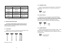
5.2 LOOPBACK TEST MODES
Selected the test modes by depressing the "Loopback Test" switch.
When in loopback mode, the "Loopback Test" LED will glow red. Two
tests are possible using this switch: Local Analog Loop (LAL) and
Remote Analog Loop (RAL).
5.2.1 LOCAL ANALOG LOOP
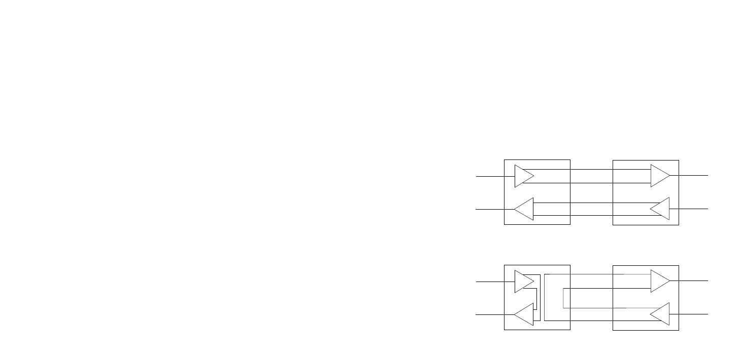
The first test mode is Local Analog Loop (V.54 Loop 3). Any data
sent to the local Model 1070 in the this mode will be echoed (returned)
back to the user device. For example, characters typed on the
keyboard of a terminal will appear on the terminal screen (see Figure 6
on the following page).
5.2.2 REMOTE ANALOG LOOP
The second test mode is Remote Analog Loop. To enter this
mode, set one of the Model 1070s (local) in test mode by depressing
the "Loopback Test" switch. Any characters sent from the remote
Model 1070 will be returned back to the originating device (see Figure
6). If no characters are echoed back, check the wiring between the two
Model 1070s. Be sure to wire the units according to the instructions in
Section 4.0 Installation.
Figure 6. Loopback Test Modes
RD
TD
TD
RD
Local 1070RC
In Normal Mode
Remote 1070RC
In Normal Mode
TX+
TX-
RX-
RX+
RX+
RX-
TX-
TX+
RD
TD
TD
RD
Local 1070RC
In Loopback Mode
Remote 1070RC
In Normal Mode
RX+
RX-
TX-
TX+
TX+
TX-
RX-
RX+
1211
Local 1070
In Normal Mode
Remote 1070
In Normal Mode
Remote 1070
In Normal Mode
Local 1070
In Loopback Mode


