


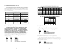
4.2.1 Four-Wire Cable Connection Via RJ-45
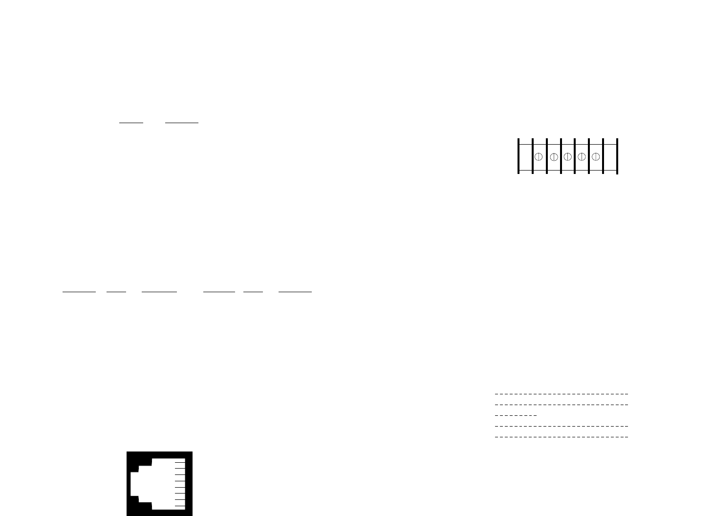
A. The RJ-45 jack on a Model 1080A/1080A-64 Short Range
Modem is prewired for a standard TELCO wiring environment. To be
sure you have the right wiring, use the table below as a guide.
RJ-45
SIGNAL
1 -------------NC
2 -------------GND
†
3 -------------RCV
4 -------------XMT
5 -------------XMT
6 -------------RCV
7 -------------GND
8 -------------NC
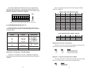
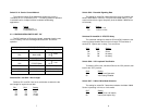
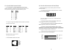
B. Proper crossing of pairs between the two modems is as follows:
†
Connection to ground is optional
SIGNAL PIN# COLOR* COLOR PIN# SIGNAL
GND
†
2 Orange ----------Brown 7 GND
RCV 3 Black -------------Green 5 XMT
XMT 4 Red ---------------Yellow 6 RCV
XMT 5 Green ------------Black 3 RCV
RCV 6 Yellow ------------Red 4 XMT
GND 7 Brown ------------Orange 2 GND
*Standard color codes—yours may be different
†
Connection to ground is optional
C. AT&T standard modular color codes:
15
1 - Blue
2 - Orange
3 - Black
4 - Red
5 - Green
6 - Yellow
7 - Brown
8 - Slate
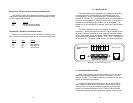
4.2.2 Four-Wire Cable Connection Via Terminal Blocks
If you are not going to use the modular jacks then follow the
instructions below.
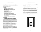
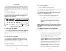
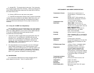
A. Locate the terminal block on the back of the unit. It should
look like the following diagram:
* The “+” and “-” indicators are for reference only. The Model 1080A Series is
not sensitive to polarity.
B. Connect one pair of wires in the telephone cable to the
Transmit lugs (TX+ and TX-) on the terminal block.
C. Connect the other pair of wires in the telephone cable to the
Receive lugs (RX+ and RX-) on the terminal block.
D. If there is a shield around the telephone cable, it may be
connected to "G" on the terminal block. We recommend connecting the
shield at the computer end only to avoid ground loops. A ground wire is
not necessary for proper operation of these units.
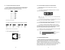
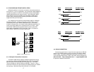
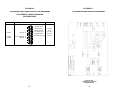
E. When you finish connecting the telephone line to units at both
ends, it should look like the following diagram:
16
XMT RCV
XMT RCV
GG
RCV XMT
RCV XMT
To Shield (Optional)
}
One Pair
}
One Pair
RX+ RX- GND TX- TX+