


4.0 INSTALLATION
The Patton Model 1203 is very simple to install.
1. Configure according to the instructions listed in Section 3.0.
2. Turn off the computer or device to which the Model 1203 is to be
connected.
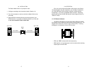
3. Plug the DB-25 connectors directly into the serial ports of your
RS-232 devices. If you wish to extend the distance, you may add
a cable not to exceed 75 feet on each side.
5.0 OPERATION
Once you have configured the Model 1203 properly (see Section
3.0) and plugged it into your equipment, you are ready to operate the
unit. After the Model 1203 is properly installed, it should operate
transparently—as if it were a standard cable connection. Operating
power is derived from the RS-232 data and control signals; there is no
“ON/OFF” switch.
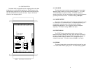
5.1 LED Status Indicators
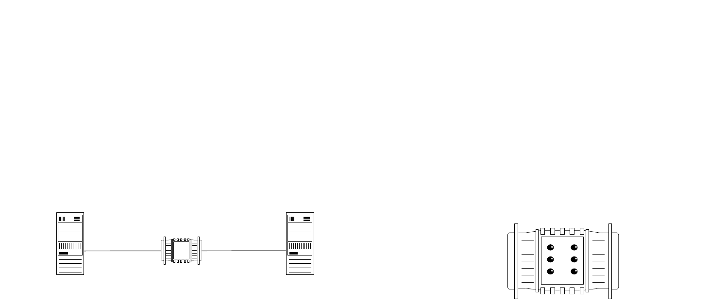
The Model 1203 features six front panel status LEDs that indicate
the condition of the modem eliminator and the communication link. The
diagram below shows the location of each of these LEDs. Following
the diagram is a description of each LED’s function.
• “TD” and “RTS” indicators blink with data activity.
• “CD” lights for an incoming signal on the line side and the resulting
output signal on the RS-232.
5 6
TD
RTS
CD
TD
RTS
CD
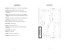
75 foot Cable
75 foot Cable
Model
1203
Sync. Host Sync. Host