


5.0 OPERATION
Once your interface converter is properly configured and installed,
it should operate transparently—as if it were a standard cable
connection. Operating power is derived from the RS-232 data and
control signals; there is no “ON/OFF” switch.
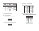
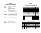
5.1 LED STATUS MONITORS
The Model 2036 and 2037 feature an easy-to-read LED that shows
the operating status of the Model 2036. Figure 1 (page 4) shows the
location of these LEDs. The following chart describes the LED’s status
codes.
Please refer to the following key to interpret the above status
codes:
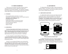
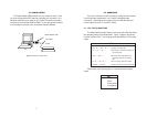
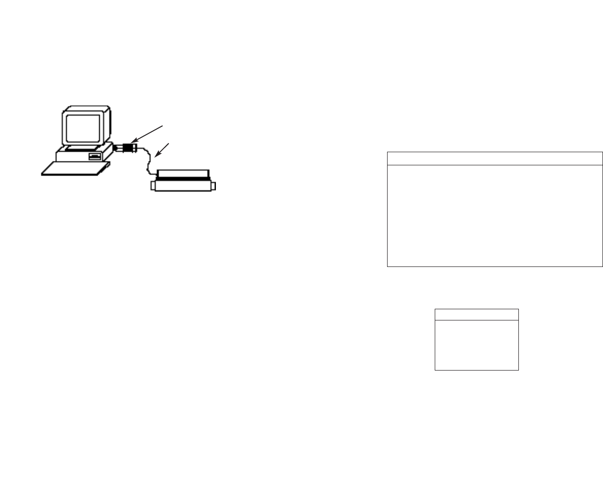
4.0 INSTALLATION
The Patton Model 2036 and 2037 are very simple to install. Once
you have configured the DIP switches, just plug your converter in to a
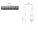
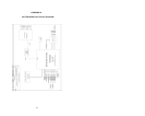
standard cable and you’re ready to go. Figure 3 illustrates the proper
connections for the Model 2036 and 2037. If you have special-ordered
a non-standard connector, your connections may be different.
7 8
LED Codes
● ● — ● ——— ● ● — ● ——— Computer is sending data
● ——— ● ——— ● ——— Serial device is connected; computer is
not sending data
● ● ——— ● ● ——— Both serial and parallel devices are
connected; computer not sending
data
● — ● ——— ● — ● ——— Printer not ready, data held in buffer
● ● ● ● ———● ● ● ● Computer ignoring flow control, data lost
Key:
● Blink
— Short pause
——— Long pause
Figure 3. Installing the Model 2036
Model 2036 or 2037
PC
Printer
Your cable