


5.1.2 LED Descriptions
The status LED blinks yellow from one to eleven times to
indicate system status. Each pulse pattern is separated by a 2
second "off " period. Greater pulse patterns have higher priority
(buffer saturation has greater priority than an empty MAC table).
Valid system statuses are:
1 pulse = system status ok
2 pulses = No MAC entries in the MAC address table
3 pulses = Clear to send (CTS) or Carrier Detect (DCD) from
base unit are not asserted
4 pulses = IMRC2/IA buffer is saturated
5 pulses = WAN receive frame(s) too large
6 pulses = WAN receive frame(s) not Octet aligned
7 pulses = WAN receive frame(s) aborted
8 pulses = Detected WAN receive frame(s) with bad CRC
9 pulses = Detected LAN receive frame(s) too large
10 pulses = Detected LAN receive frame(s) not Octet aligned
11 pulses = Detected LAN receive frame(s) with bad CRC
After a status code is displayed eight times and the associ-
ated condition is removed, the status code will no longer appear.
The link LED glows green to indicate link integrity on the
10BaseT twisted pair line.
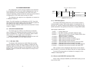
5.1.3 Power and DCE/DTE Interface LEDs
Seven LEDs indicate POWER and DTE/DCE activity on the
front of the 2135.
9
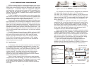
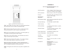
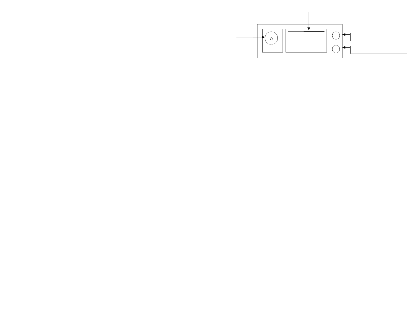
Green LED, link integrity
Yellow LED, Status
Figure 4. 2135 rear view
RJ-45 Jack, 10BaseT connection
POWER
JACK
5.0 CONFIGURATION
All configuration is done through software auto-detection
for the Model 2135. Once you have configured your mux or
other equipment to be connected to the 2135, the unit is
ready for operation. Observe that the serial port of the 2135 is
configured as a DTE and must connect to a DCE.
The LAN port also requires no configuration to connect to
a 10BaseT Ethernet.
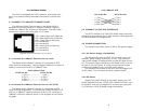
Note: The V.35 Interface is configured as a DTE. The 2135
will transmit and receive data to and from the DCE, based on
the speed of the clocks received from the DCE.
On the LAN side interface, data is sent and received in burst
mode at 10Mbps.
5.1 LED STATUS MONITORS
The 2135 uses two LEDs on the Ethernet connection
side. A green LED indicates that link connection to the net-
work is established. The yellow LED displays status codes
(See section 5.1.2 for status code information).
Seven, low power, LEDs located on the top of the 2135
case indicate POWER and V.35 signal activity.
5.1.1 LAN side LEDs
The Model 2135 features two LAN LEDs that monitor
general operation status and the 10BaseT twisted pair link
integrity. Figure 4 shows the LEDs located at the rear of the
Model 2135. Following Figure 4 is a description of each LED
function. Figure 5 shows the LEDs located on the top of the
Model 2135.
10