


15
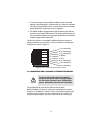
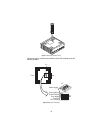
5.2 FRONT PANEL LED STATUS MONITORS
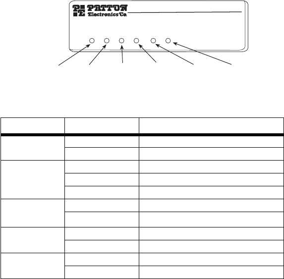
The Model 2158B features six front panel LEDs that monitor power, the
Ethernet signals, the CopperLINK connection, and the remote/local set-
ting. Figure 7 shows the front panel location of each LED. Table 2 on
page 15 describes the LED functions.
Figure 7.
Model 2158B front panel
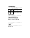
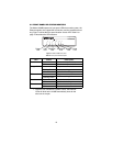
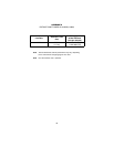
Table 2:
Front panel LED description
LED Status Description
Power
Green The device is powered on.
Off The device is powered off.
CopperLink
Green The port is connected.
Blinking Green Data transceiving.
Off No valid link on this port.
Ethernet
Green The port is connected.
*
Blinking Green
*.
Once the unit connects to a power source, the Ethernet
LEDs will blink as the 2158B automatically looks for the
other unit in the pair.
Data transceiving.
Local
Green The device acts in Local mode.
Off Local mode is off.
Remote
Green The device acts in Remote mode.
Off Remote mode is off.
Power
LED
Link
LED
Ethernet 1
LED
Ethernet 2
LED
CopperLINK
Ethernet Extender
P
o
w
e
r
L
i
n
k
E
t
h
e
r
n
e
t
1
E
t
h
e
r
n
e
t
2
R
e
m
o
t
e
L
o
c
a
l
Remote
LED
Local
LED